Fiber optic tracking system and method for tracking

a tracking system and fiber optic technology, applied in the field of fiber optic tracking system, can solve the problems of high sampling rate, high accuracy, and inability to provide seamless integration

Active Publication Date: 2009-12-24
MAKO SURGICAL CORP
View PDF26 Cites 73 Cited by
  • Summary
  • Abstract
  • Description
  • Claims
  • Application Information

AI Technical Summary

Problems solved by technology

Disadvantages of such conventional surgical navigation technologies can include the failure to provide seamless integration; high accuracy; high sampling rate; robust tracking capability that is not easily affected by a surgical procedure or by the surgical workflow; and tracking of any combination of, for example, patient anatomy, surgical instruments, the surgical robotic arm, bone cutting instruments, and other objects.

Method used


Image

  • Fiber optic tracking system and method for tracking
  • Fiber optic tracking system and method for tracking
  • Fiber optic tracking system and method for tracking

Examples


Embodiment Construction

[0031]Presently preferred embodiments of the invention are illustrated in the drawings. An effort has been made to use the same or like reference numbers throughout the drawings to refer to the same or like parts. Although the specification refers primarily to surgical systems, it should be understood that the subject matter described herein is applicable to the tracking of objects in general.

Overview of the Fiber Optic Tracking System

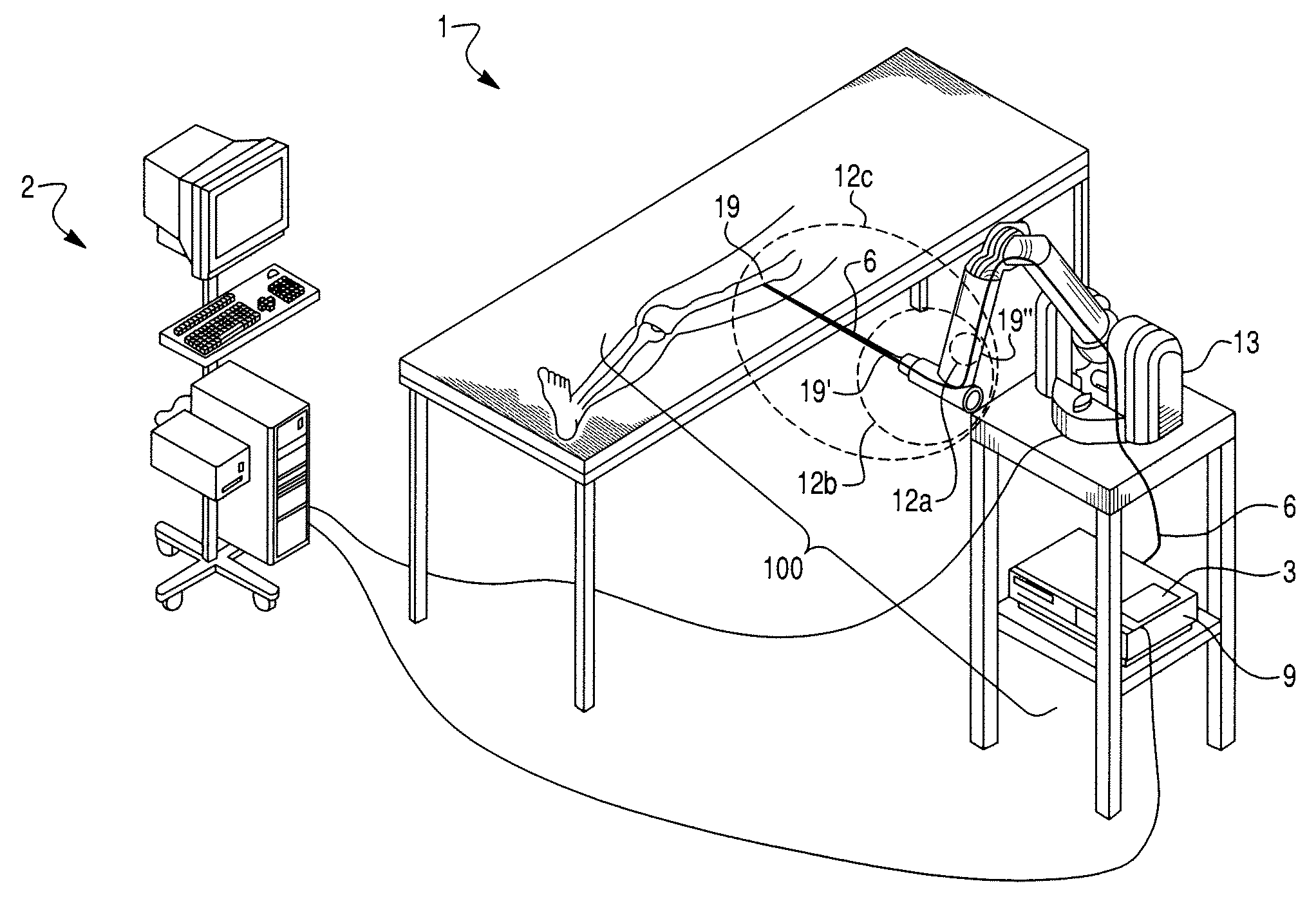
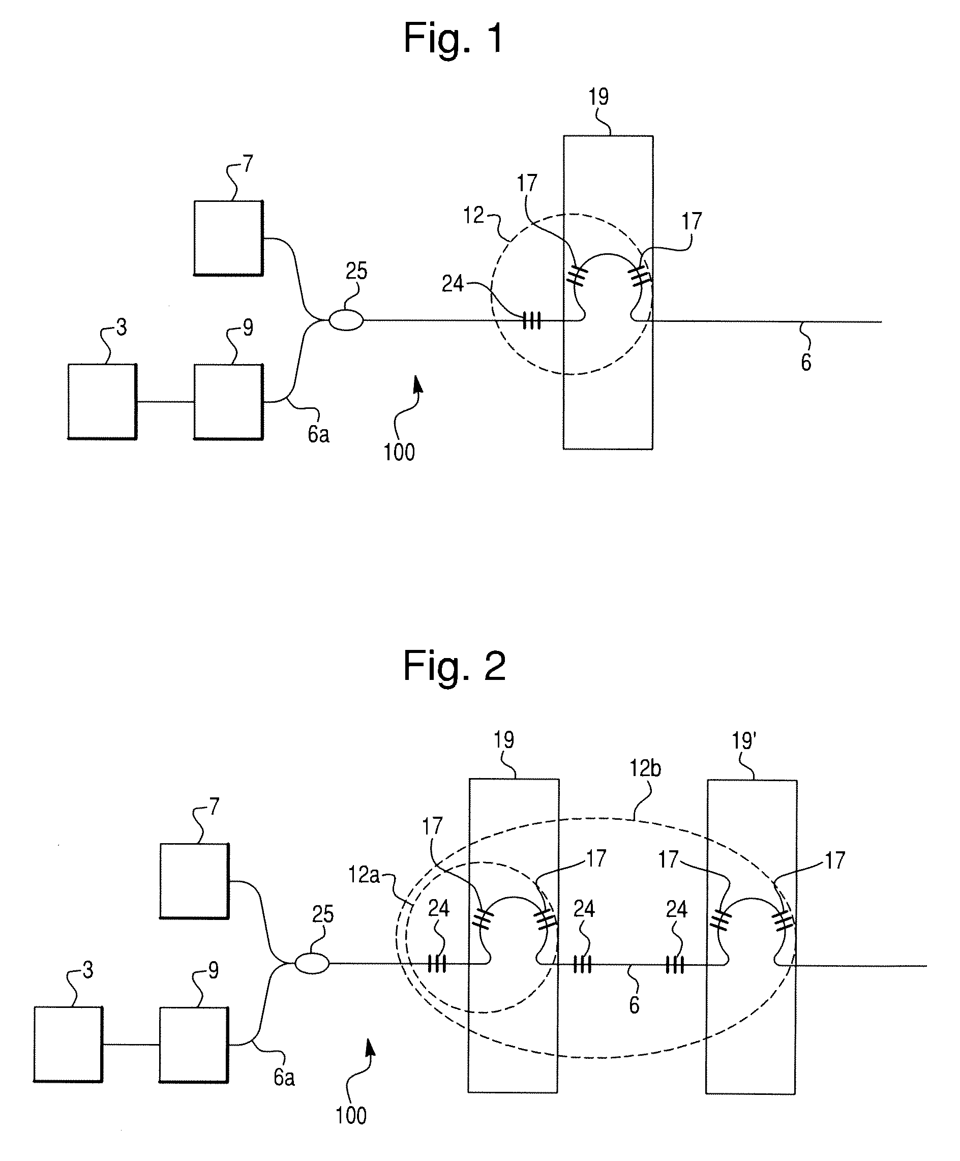
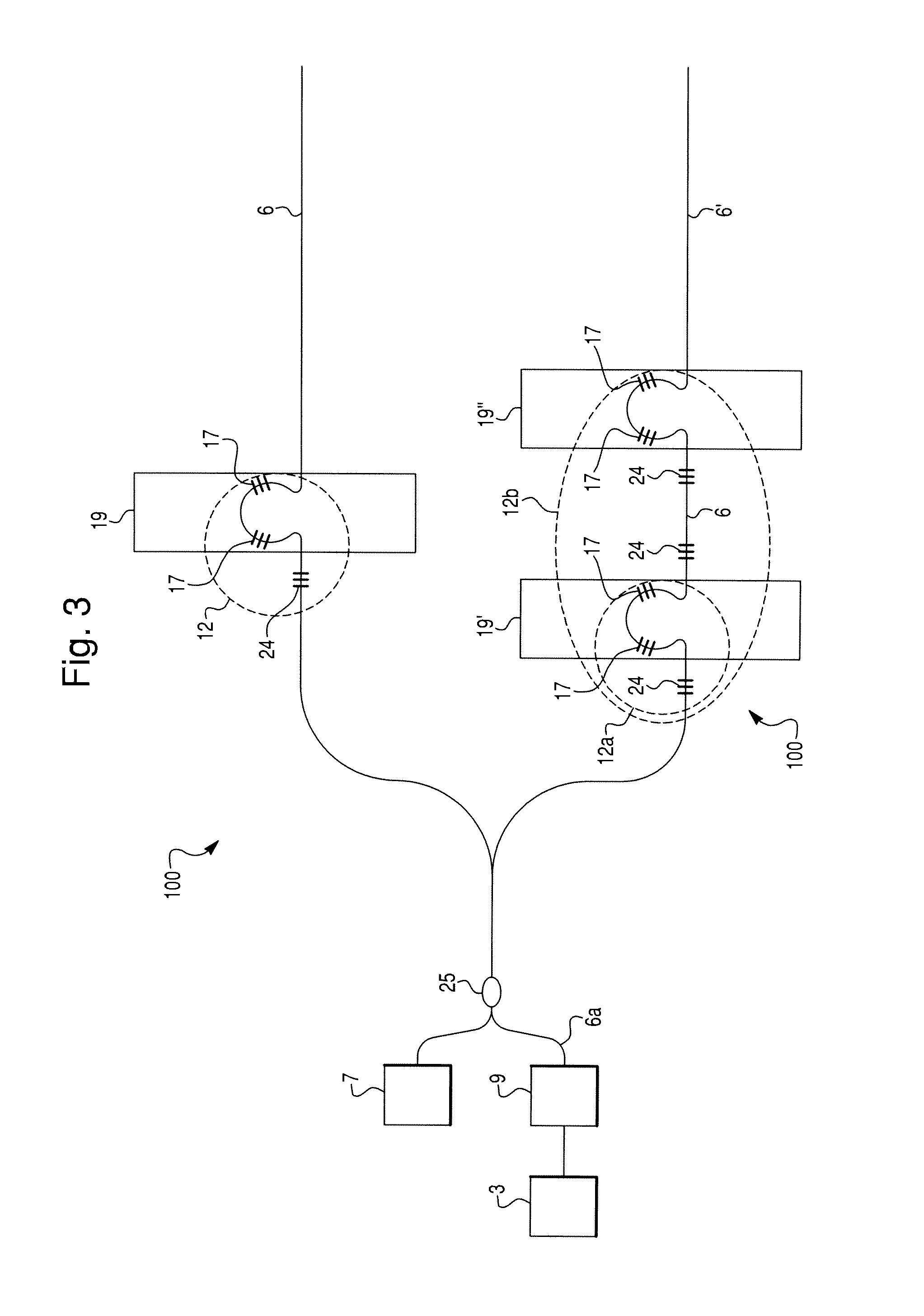
[0032]Referring to FIGS. 1 and 2, a fiber optic tracking system 100 according to an embodiment of the present invention preferably includes a light source 7, an optical fiber 6 with at least one sensing component 12, a detection unit 9, and a calculation unit 3. In this application, the reference numeral 12 is used generically to refer to a sensing component, and the reference characters 12a, 12b, 12c, 12′, etc. are used to distinguish between specific sensing components. Each of these portions or components of the fiber optic tracking system 100 will ...


PUM


Abstract

A fiber optic tracking system for tracking substantially rigid object(s) is described. The fiber optic tracking system includes a light source, an optical fiber having a sensing component configured to modify optical signals from the light source, the optical fiber being configured to attach to the substantially rigid object, a detection unit arranged to receive the modified optical signals from the sensing component, and a calculation unit configured to determine a pose of the substantially rigid object in six degrees of freedom based on the modified optical signals.

Description

CROSS-REFERENCE TO RELATED PATENT APPLICATIONS[0001]This application claims priority from U.S. Provisional Patent Application Ser. No. 61 / 132,446, filed Jun. 18, 2008, which is incorporated herein by reference in its entirety.BACKGROUND OF THE INVENTION[0002]1. Field of Invention[0003]The invention relates to a fiber optic tracking system for tracking a substantially rigid object and a method for tracking a substantially rigid object using a fiber optic tracking system.[0004]2. Description of Related Art[0005]It is often necessary to determine or track the position of an object. For example, computer assisted surgical systems have been developed that use robotic devices that are precise and can greatly improve surgical procedures. Proper performance of those devices requires the tracking of positions of objects, such as portions of the human anatomy, surgical instruments, and portions of the robotic device.[0006]There are several conventional surgical navigation technologies that ar...

Claims


Application Information

Patent Timeline
Patent Type & Authority Applications(United States)
IPC IPC(8): G01C21/02G02B6/00
CPCA61B19/2203A61B19/5244A61B2019/467G02B6/02057A61B2019/5259A61B2019/5483G02B6/02042A61B2019/5255A61B2090/3983A61B2034/2055A61B34/20A61B2090/067A61B34/30A61B2034/2059A61B2034/2061
Inventor VAN VORHIS, ROBERTHAGAG, BENNYKANG, HYOSIGLIGHTCAP, CHRISABOVITZ, RONY
Owner MAKO SURGICAL CORP
Why Eureka
Try Eureka