Magnetic element

a technology of magnetic elements and winding shafts, applied in the direction of transformers/reacts, inductances, cores/yokes, etc., can solve the problems of difficult drawing out of the end portion of the coil wound on the winding shaft of the drum core, and the size of the magnetic element is reduced, and the task of connecting the coil and the terminal is facilitated. , the effect of easy drawing ou

Inactive Publication Date: 2009-12-24
SUMIDA CORP
View PDF11 Cites 2 Cited by
  • Summary
  • Abstract
  • Description
  • Claims
  • Application Information

AI Technical Summary

Benefits of technology

[0006]According to an embodiment of the present invention, there is provided a magnetic element which is small in size and in which a coil and a terminal can be connected easily.
[0012]According to embodiments of the present invention, the size of the magnetic element can be reduced since the magnetic element is configured such that the flange portion of the drum core is partially engaged with the shield core. In addition, the task of connecting the coil and the terminal is facilitated since the end portion of the coil wound on the drum core can be easily drawn out.

Problems solved by technology

Moreover, there is such a problem that the layout area of the magnetic element becomes large when the magnetic element is mounted on a substrate.
In addition, since the ring core surrounds the drum core, there is such a problem that an end portion of the coil wound on the winding shaft of the drum core is difficult to draw out toward a terminal side at the time of connecting the terminal and the coil.

Method used


Image

  • Magnetic element
  • Magnetic element
  • Magnetic element

Examples


first embodiment

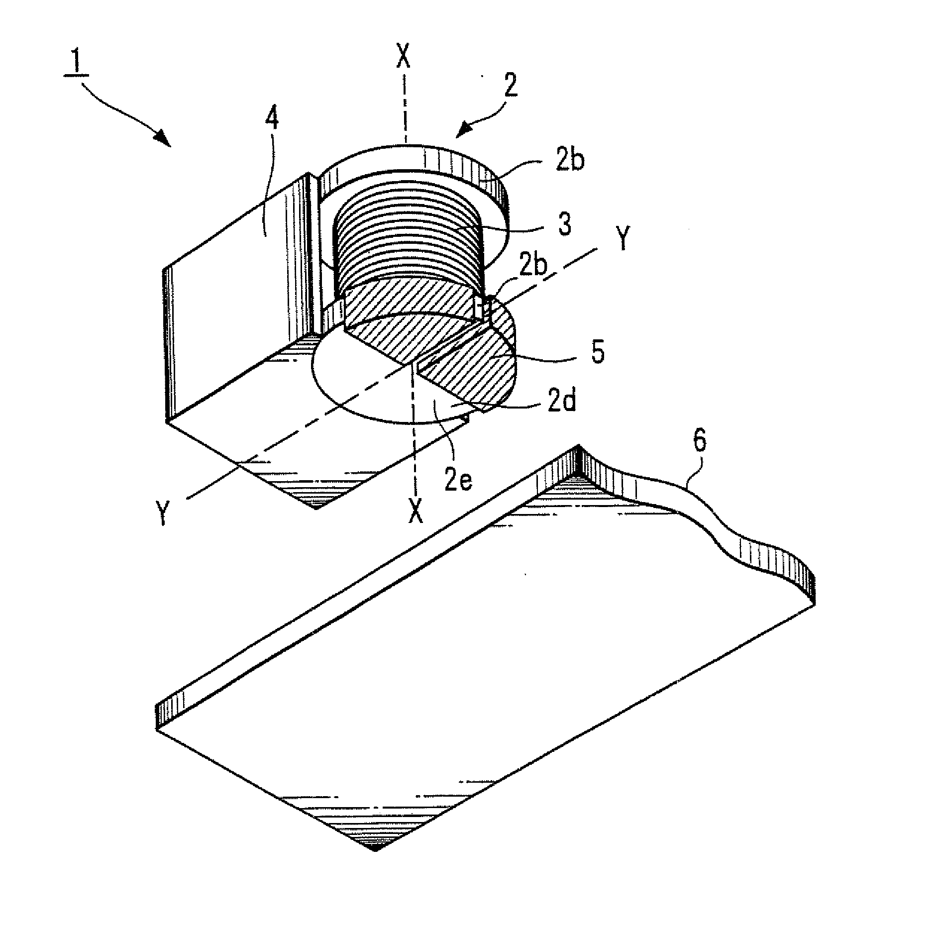
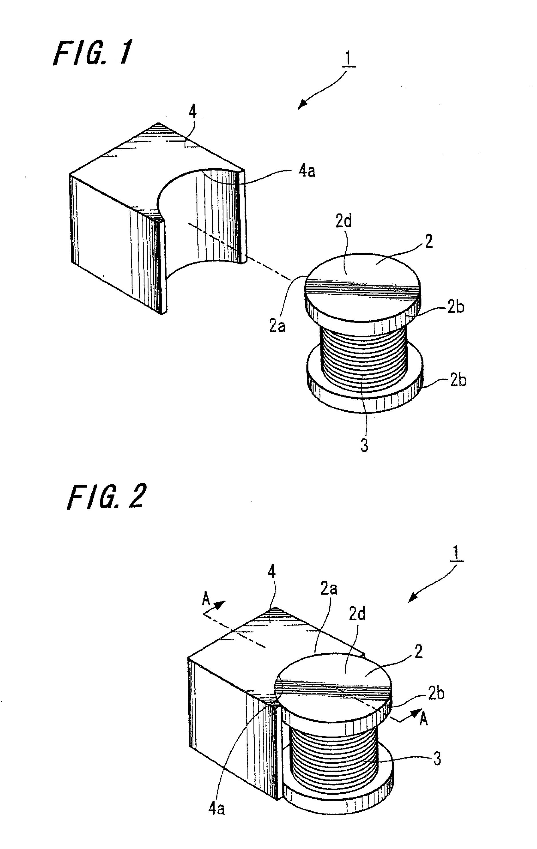
[0024]FIG. 1 is an exploded perspective view of a magnetic element according to the present invention.

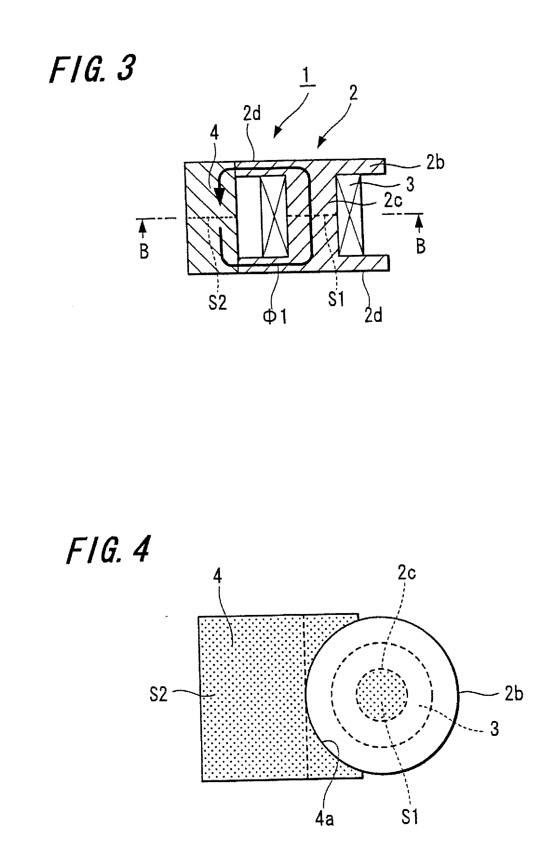
[0025]As shown in FIG. 1, an inductance element 1 as the magnetic element is configured to have a drum core 2, a coil 3 and a shield core 4.

[0026]The drum core 2 includes a winding shaft and flange portions 2b having planar flange surfaces 2d. The drum core 2 is made of a magnetic material using Ni—Zn type ferrite. Further, the coil 3 is wound on the winding shaft (not illustrated) that is connected contiguously with the flange portions 2b.

[0027]In addition, a terminal (not illustrated) to connect with each end portion of the coil 3 is provided in the drum core 2. The terminal may be formed such that a metallic terminal member is attached to the drum core or such that a terminal electrode is printed on the drum core by using Ag paste. Also, the terminal electrode may be provided in the shield core 4.

[0028]The shield core 4 is formed such that the height thereof approximately corres...

second embodiment

[0048]FIG. 6 is a perspective view when a magnetic element according to the present invention is mounted on a mounting substrate.

[0049]In FIG. 6, the same reference numerals are given to those corresponding to FIG. 2 and duplicated explanations thereof are omitted.

[0050]As shown in FIG. 6, a shield core 4′ in this embodiment is formed such that the height thereof approximately corresponds to the height of the drum core 2, and an engagement portion 4′a having a shape that matches with the outer circumferential shape 2a of the flange portion 2b is formed on one surface opposing the drum core 2. In this embodiment, the engagement portion 4′a is formed with a semi-cylindrical concave portion since the outer circumferential shape 2a of the flange portion 2b is circular.

[0051]In addition, the shield core 4′ is formed with such a size that the width in a radial direction of the flange portion 2b is approximately the same along the outer circumference of the flange portion 2b. Thereby, the ...

third embodiment

[0053]FIG. 7 is a cross-sectional view of a magnetic element according to the present invention.

[0054]In FIG. 7, the same reference numerals are given to those corresponding to FIG. 3 and duplicated explanations thereof are omitted.

[0055]As shown in FIG. 7, an inductance element 11 is configured to have a so-called T-shaped drum core 12, a coil 3 wound on a winding shaft 12c of the drum core, and a shield core 14.

[0056]The drum core 12 includes a winding shaft 12c and a flange portion 12b that is connected contiguously with only one end of the winding shaft 12c.

[0057]The shield core 14 includes a main body portion 14a that opposes the drum core 12 and a tabular seat portion 14d that is connected contiguously with the bottom side of the main body portion 14a, and the shield core 14 is formed such that a cross-sectional plane thereof has a so-called L-shape as shown in the figure. The inductance element 11 is assembled such that an end portion 12f of the winding shaft 12c on the side...


PUM

PropertyMeasurementUnit
circumferenceaaaaaaaaaa
areaaaaaaaaaaa
cross-sectional areaaaaaaaaaaa

Abstract

A magnetic assembly includes a mounting substrate and a magnetic element mounted on the mounting substrate. The magnetic element includes a drum core provided with a flange portion at each end of a winding shaft, a coil wound on the winding shaft, and a shield core engaged with the drum core, the shield core including an engagement portion having a shape that corresponds to the shape of a portion of the outer circumference of at least one of the flange portions so that the engagement portion mates with the at least one flange portion.

Description

CROSS REFERENCES TO RELATED APPLICATIONS[0001]This application is a divisional of U.S. patent application Ser. No. 11 / 796,390, filed on Apr. 27, 2007, and claims priority to Japanese Patent Application No. P2006-filed on Apr. 28, 2006, the disclosures of which are hereby incorporated by reference herein.BACKGROUND OF THE INVENTION[0002]The present invention relates to a magnetic element and more particularly relates to an inductance element that is used for a power supply.[0003]In the past, there have been known many magnetic elements which have such a structure that a rectangular or cylindrical ring core is disposed around a circular drum core having a coil wound on a winding shaft (refer to Japanese Unexamined Patent Publication No. 2006-73847, for example).[0004]However, in the magnetic element having the above-described structure, the magnetic element becomes a large size since the rectangular or cylindrical ring core is disposed around the circular drum core and therefore the m...

Claims


Application Information

Patent Timeline
Patent Type & Authority Applications(United States)
IPC IPC(8): H01F27/06
CPCH01F3/10H01F27/365H01F17/045H01F3/12H01F27/36H01F27/366
Inventor SANO, KAN
Owner SUMIDA CORP
Why Eureka
Try Eureka