Vessel monitoring system

a monitoring system and vessel technology, applied in the field of vessel monitoring systems, can solve the problems of not being able to acquire a target vessel with an insufficient reflection intensity of radar waves, not being able to immediately determine, and people on the bridge may not correctly acquire the depth

Inactive Publication Date: 2009-12-24
FURUNO ELECTRIC CO LTD
View PDF6 Cites 23 Cited by
  • Summary
  • Abstract
  • Description
  • Claims
  • Application Information

AI Technical Summary

Benefits of technology

[0015]Further, in the vessel monitoring system according to the present invention, the display unit is configured to display an expected course line indicating an expected course extended from a current position of the target vessel, thereby allowing immediate identification of correspondence between an encounter position and the target vessel which the own vessel is to encounter at the encounter position.
[0020]According to the vessel monitoring system of the present invention, the following effects may be achieved.
[0021]In a trial navigation by provisionally setting a course and a value of a speed of an own vessel arbitrarily, a display unit is configured to display an OZT corresponding to the arbitrarily and provisionally set course and value of the speed of the own vessel. Therefore, with a trial navigation by provisionally setting a course and a value of a speed of the own vessel arbitrarily, it is possible to prevent the own vessel from interfering a target vessel promptly without fail, as well as to approach a desired target vessel in the shortest time by the most suitable course and most suitable speed.

Problems solved by technology

However, when the target vessel is located far away, the person on the bridge may not correctly acquire the depth, i.e. the distance between the own and target vessels.
However, due to the characteristics of the radar waves, it may not possible in some cases to acquire a target vessel with an insufficient reflection intensity of the radar waves.
Therefore, when attempting to collect the relative position information of the target vessel using these devices separately and simultaneously, the person on the bridge may encounter a situation in which it is not possible to immediately determine which piece of relative position information acquired by one identification device for one target vessel corresponds to a piece of relative position information acquired by a different identification device for the target vessel.
In particular, in a situation in which there are a number of vessels densely under way within a visual field of the person on the bridge, it becomes even more difficult to determine if the target vessel acquired by one identification device is the same vessel as the one acquired by another identification device.
This poses a very serious problem in view of ensuring the secure navigation of vessels (see Patent Document 1).

Method used


Image

  • Vessel monitoring system
  • Vessel monitoring system
  • Vessel monitoring system

Examples


Embodiment Construction

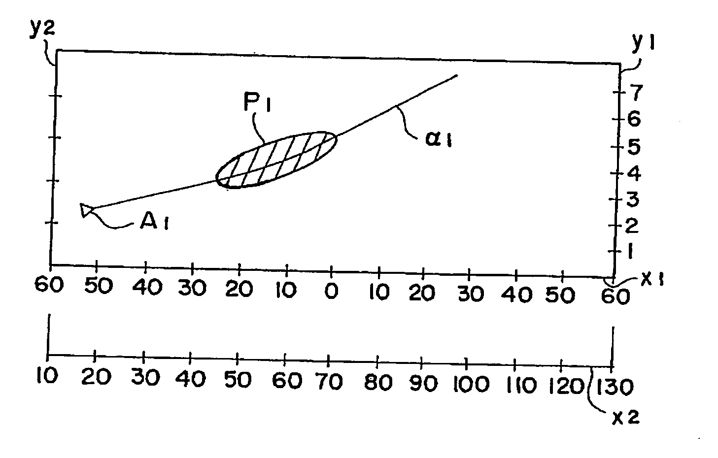
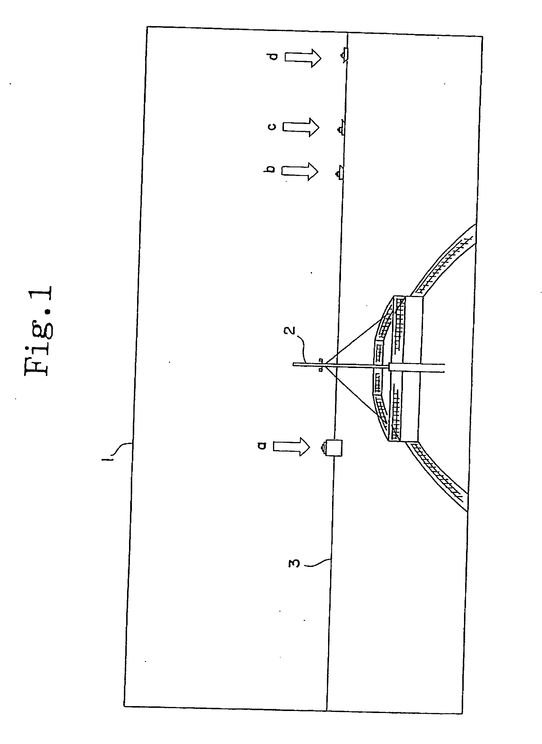
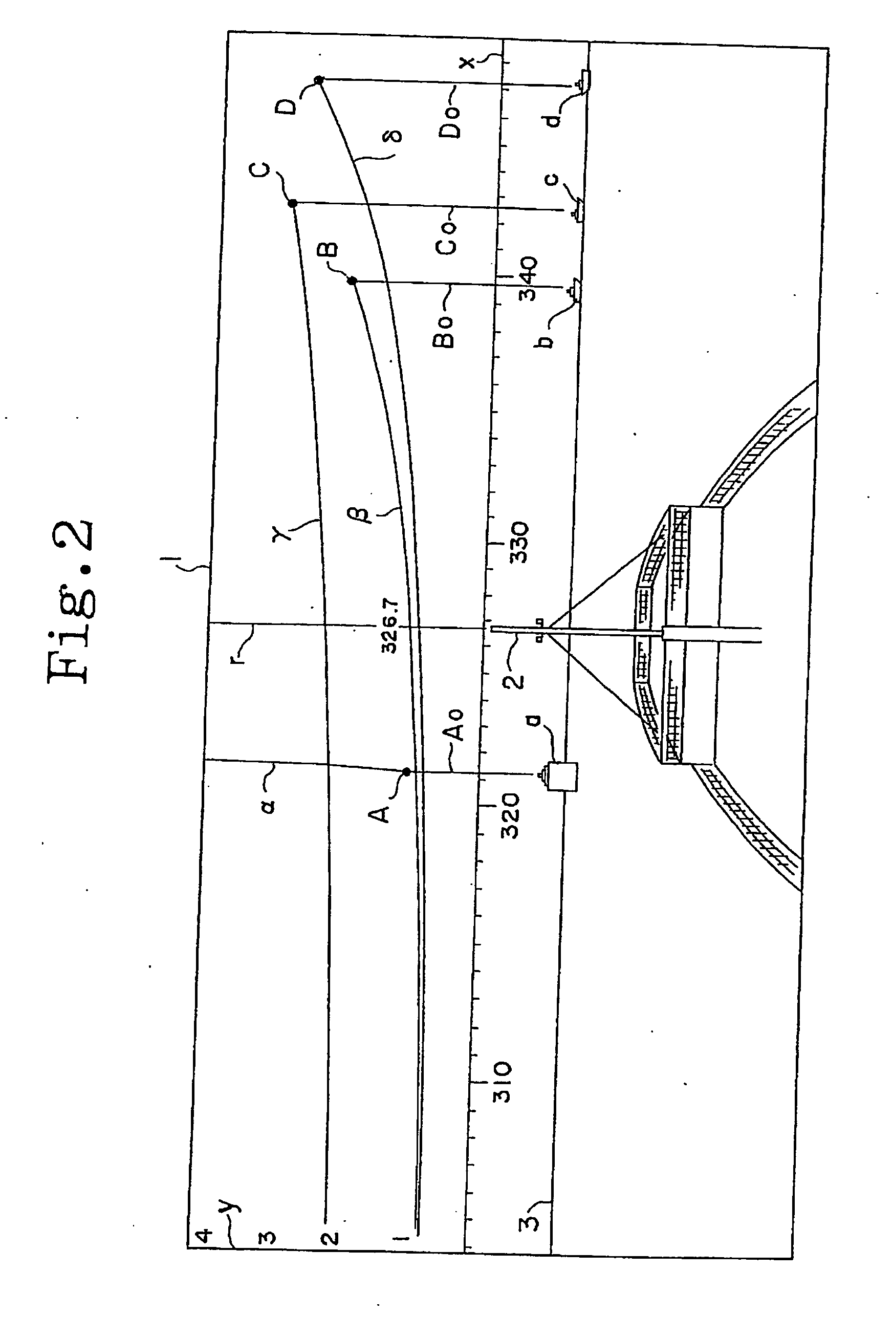
[0032]The following describes an embodiment of the present invention with reference to the drawings. FIG. 1 illustrates an explanatory display screen displaying an example of landscape on the water viewed from an own vessel that is virtually reproduced. FIG. 2 illustrates the display screen of FIG. 1 overlaid with, according to the present invention, a direction-distance coordinate, a radar image after coordinate transformation, and a positional image, which is produced after coordinate transformation, of positional information of target vessels acquired by an Automatic Identification System. FIG. 3 illustrates a view for explaining the basic idea of an Obstacle Zone by Targets (OZT) according to the present invention. FIG. 4 illustrates an example of the display screen of FIG. 2 overlaid with the OZT after coordinate transformation according to the present invention.

[0033]First, referring to FIG. 1, a display screen 1 of a navigation aid system according to the present invention di...


PUM


Abstract

The vessel monitoring system has, in a trial navigation by provisionally setting a value of the speed of the own vessel arbitrarily, a display unit immediately display an Obstacle Zone by Targets (OZT) corresponding to the speed of the own vessel.The vessel monitoring system includes a calculator for calculating an Obstacle Zone by Targets, a display unit for displaying the Obstacle Zone by Targets obtained by the calculation by the calculator, and an integrated controller for processing trial navigation that integrally controls mutually cooperated processing of calculation by the calculator and display by the display unit, in a trial navigation by provisionally setting a value of the speed of the own vessel arbitrarily, so that the calculator calculates an Obstacle Zone by Targets corresponding to the arbitrarily and provisionally set value of the speed of the own vessel, and the display unit displays the result of the calculation.

Description

TECHNICAL FIELD[0001]The present invention relates to a vessel monitoring system configured to have a calculator to calculate an Obstacle Zone by Targets (OZT) corresponding to a speed of an own vessel when provisionally setting the speed of the own vessel to a given value, and to have a display unit to display the result of the calculation.BACKGROUND ART[0002]As devices used to recognize vessels on the water, there have been conventionally known a radar detection system using radar and equipped on an own vessel and an Automatic Identification System based on information transmitted from target vessels in addition to visual monitoring by a person on the bridge.[0003]When using the visual monitoring, the person on the bridge acquires a target vessel in three dimensions, and sensuously recognizes relative position information of the target vessel based on the direction and distance of the target vessel from the own vessel. However, when the target vessel is located far away, the perso...

Claims


Application Information

Patent Timeline
Patent Type & Authority Applications(United States)
IPC IPC(8): B63B49/00B63B43/18
CPCB63B49/00B63B43/18G08G3/02G01S13/937
Inventor IMAZU, HAYAMAAKAMATSU, AKIOYOSHIOKA, TAKASHIOHSHIMA, HISAICHIKIYA, YOSHIYUKIKAWAMOTO, TAKUMI
Owner FURUNO ELECTRIC CO LTD
Why Eureka
Try Eureka