Image display apparatus and image display method
a technology of image display and image, which is applied in the direction of printers, cameras, instruments, etc., can solve the problems of inability to accurately adjust the focus of scanning light, inability to achieve image formation on the retina, and extremely small amount of reflected light from the retina
- Summary
- Abstract
- Description
- Claims
- Application Information
AI Technical Summary
Benefits of technology
Problems solved by technology
Method used
Image
Examples
first embodiment
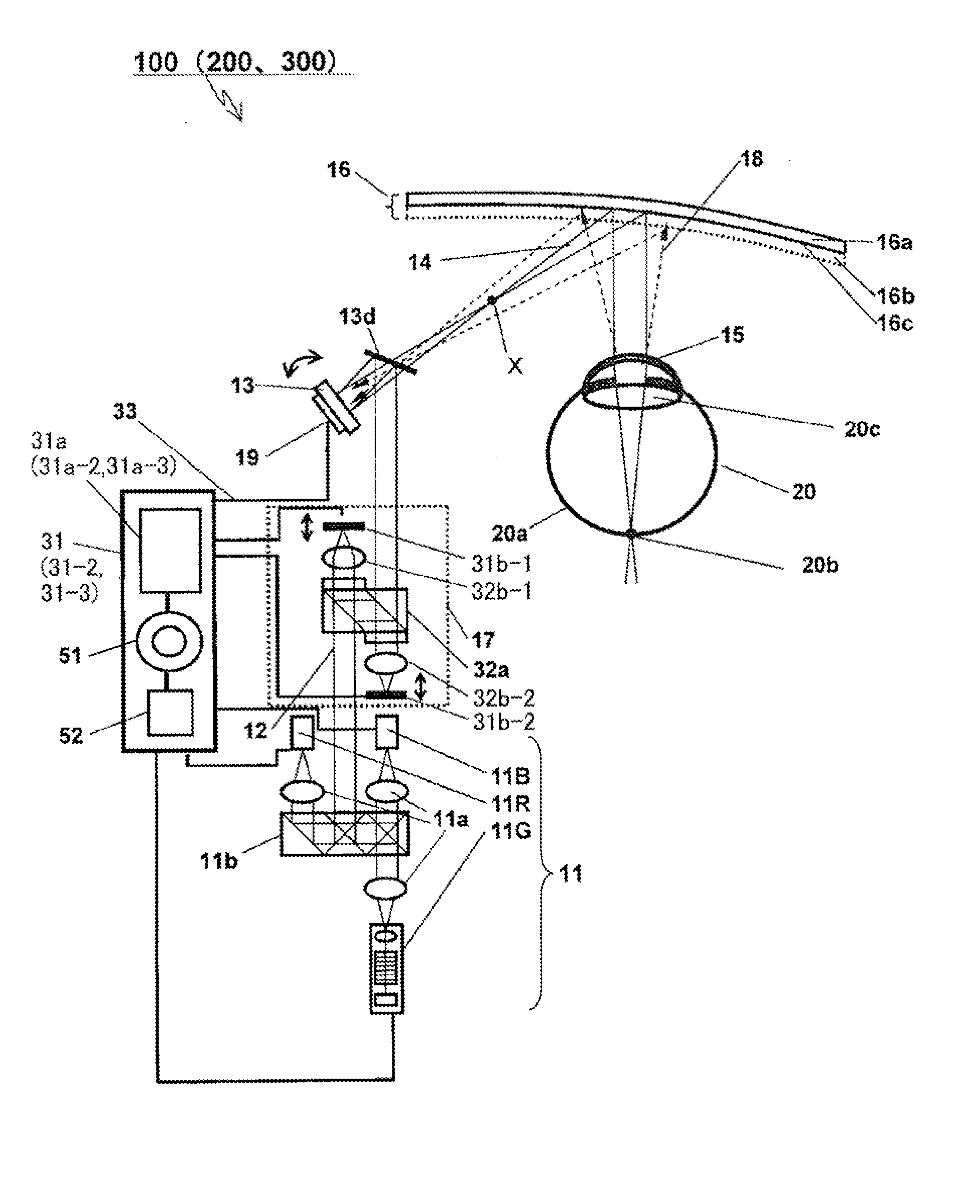
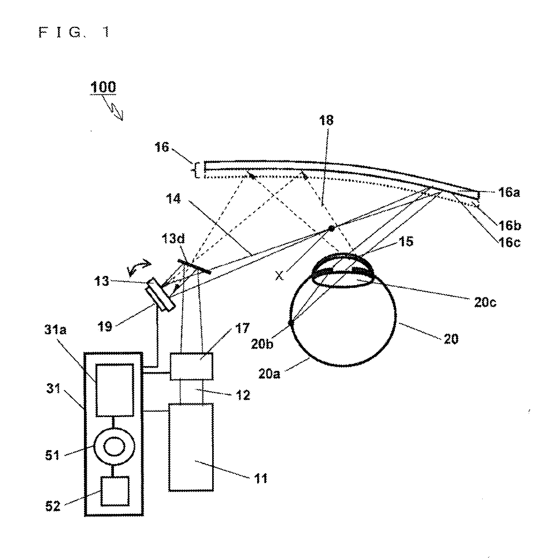
[0034]FIG. 1 shows an example of a schematic configuration of an image display apparatus 100 according to a first embodiment. First, the image display apparatus 100 will be described briefly with reference to FIG. 1. As shown in FIG. 1, the image display apparatus 100 Includes a laser light source 11, a focus position adjustment section 17, a reflection mirror 13d, a scanning section 13, a light deflection section 16, a light detection section 19, and a control part 31. The control part 31 includes a control section 31a, an adjustment section 51, and a storage section 52. In FIG. 1, an eye 20 of a viewer (hereinafter, referred to as a user) whose eye is scanned is shown.
[0035]The laser light source 11 emits laser light 12 for projecting an image on the retina 20a of the eye 20, and changes the intensity and the color of the laser light 12 in accordance with control of the control part 31.
[0036]The focus position adjustment section 17 adjusts the focus position of the laser light 12 ...
second embodiment
[0080]In addition to the features of the image display apparatus 100 according to the first embodiment, an image display apparatus 200 according to a second embodiment has a feature of detecting the view line direction of a user, providing a clear image in a region (a central visual region of the user) corresponding to the detected view line direction, and providing a relatively unclear image in the other regions (a peripheral visual region of the user).
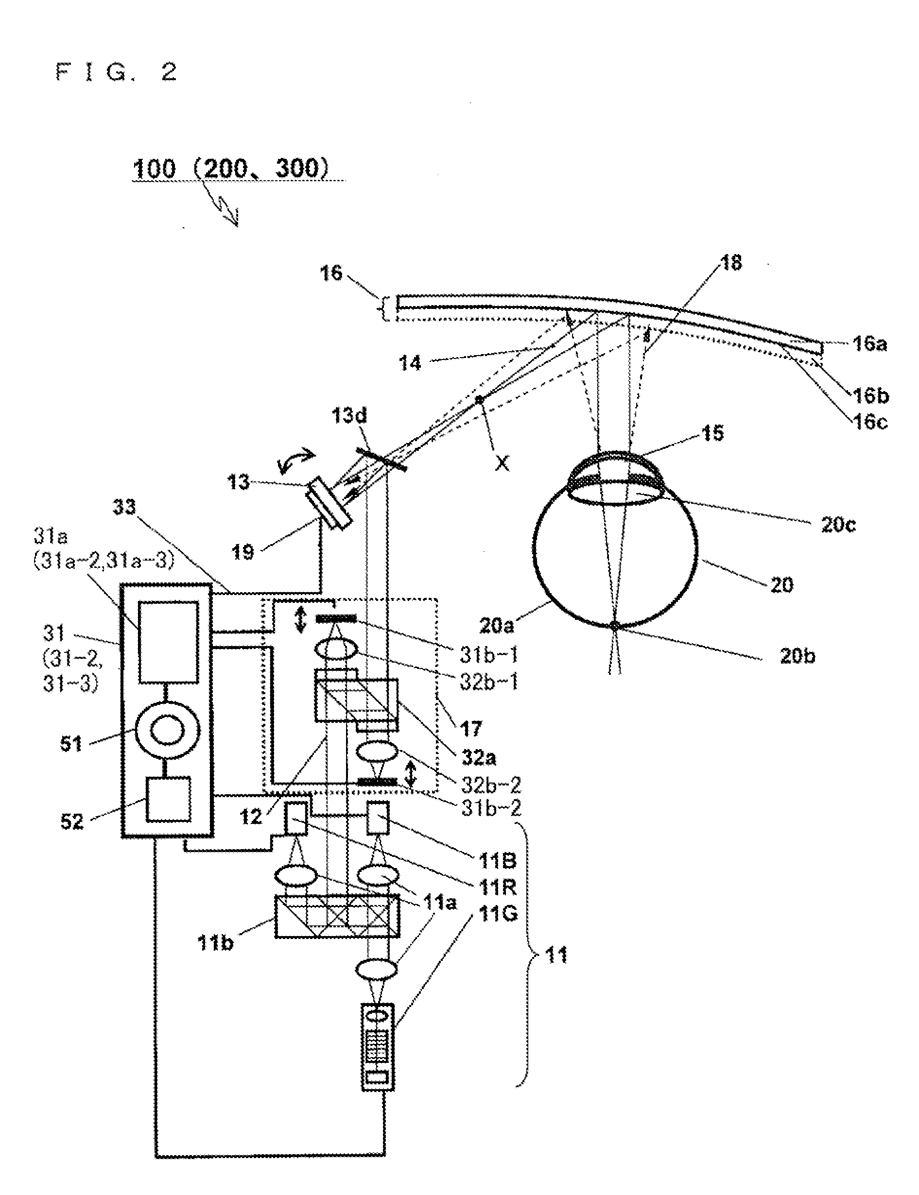
[0081]The image display apparatus 200 according to the second embodiment has a configuration in which the control part 31 of the image display apparatus 100 according to the first embodiment is replaced with a control part 31-2. The control part 31-2 of the image display apparatus 200 has a configuration in which the control section 31a of the control part 31 of the image display apparatus 100 is replaced with a control section 31a-2. Thus, the following will describe the difference from the image display apparatus 100 according to t...
third embodiment
[0086]In addition to the features of the image display apparatus 100 according to the first embodiment, an image display apparatus 300 according to a third embodiment has a feature of detecting the view line direction of a user, and changing an initial setting signal, used for focus adjustment, so as to follow a change of the view line direction.
[0087]The image display apparatus 300 according to the third embodiment has a configuration in which the control part 31 of the image display apparatus 100 according to the first embodiment is replaced with a control part 31-3. The control part 31-3 of the image display apparatus 300 has a configuration in which the control section 31a of the control part 31 of the image display apparatus 100 is replaced with a control section 31a-3. Thus, the following will describe the difference from the image display apparatus 100 according to the first embodiment with reference to FIG. 2. For the same content as that of the image display apparatus 100 a...
PUM
 Abstract
Description
Claims
Application Information
 - R&D
- Intellectual Property
- Life Sciences
- Materials
- Tech Scout
- Unparalleled Data Quality
- Higher Quality Content
- 60% Fewer Hallucinations
Browse by: Latest US Patents, China's latest patents, Technical Efficacy Thesaurus, Application Domain, Technology Topic, Popular Technical Reports.
© 2025 PatSnap. All rights reserved.Legal|Privacy policy|Modern Slavery Act Transparency Statement|Sitemap|About US| Contact US: help@patsnap.com


