Optical pickup device

a pickup device and optical technology, applied in the field of optical pickup devices, can solve the problem that the accurate focus control cannot be carried out, and achieve the effect of reducing the effect of reflected light and correcting the spherical aberration

Inactive Publication Date: 2006-05-18
SHARP KK
View PDF9 Cites 9 Cited by
  • Summary
  • Abstract
  • Description
  • Claims
  • Application Information

AI Technical Summary

Benefits of technology

[0035] In order to solve this problem, according to the foregoing arrangement, the auxiliary light receiving regions are made shorter than the main light receiving regions in the drawing direction of the division line. This makes it possible to prevent such a problem that, although the return light from the non-recording layer is not projected on the main light receiving regions, the return light from the non-recording layer is projected only on the auxiliary light receiving regions. Therefore, even when recording / reproducing operation is carried out with respect to the multilayer optical disk, it is possible to minimize an effect of reflected light from the non-recording layer and to correct the spherical aberration. This makes it possible to properly carry out focus adjustment.

Problems solved by technology

In this case, an offset occurs, so that accurate focus control cannot be carried out.

Method used


Image

  • Optical pickup device
  • Optical pickup device
  • Optical pickup device

Examples


first embodiment

[0055] One embodiment of the present invention will be described below with reference to the drawings.

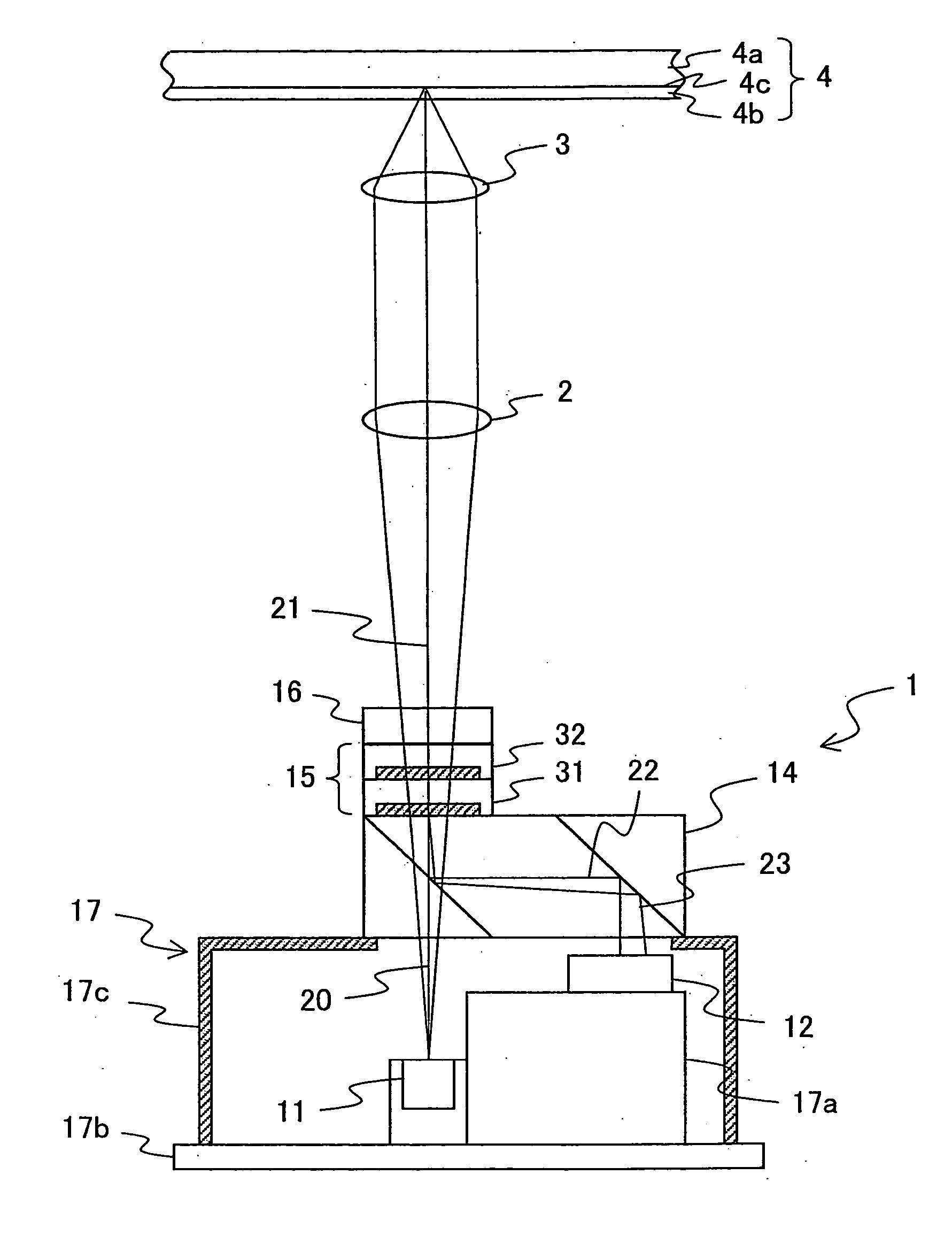
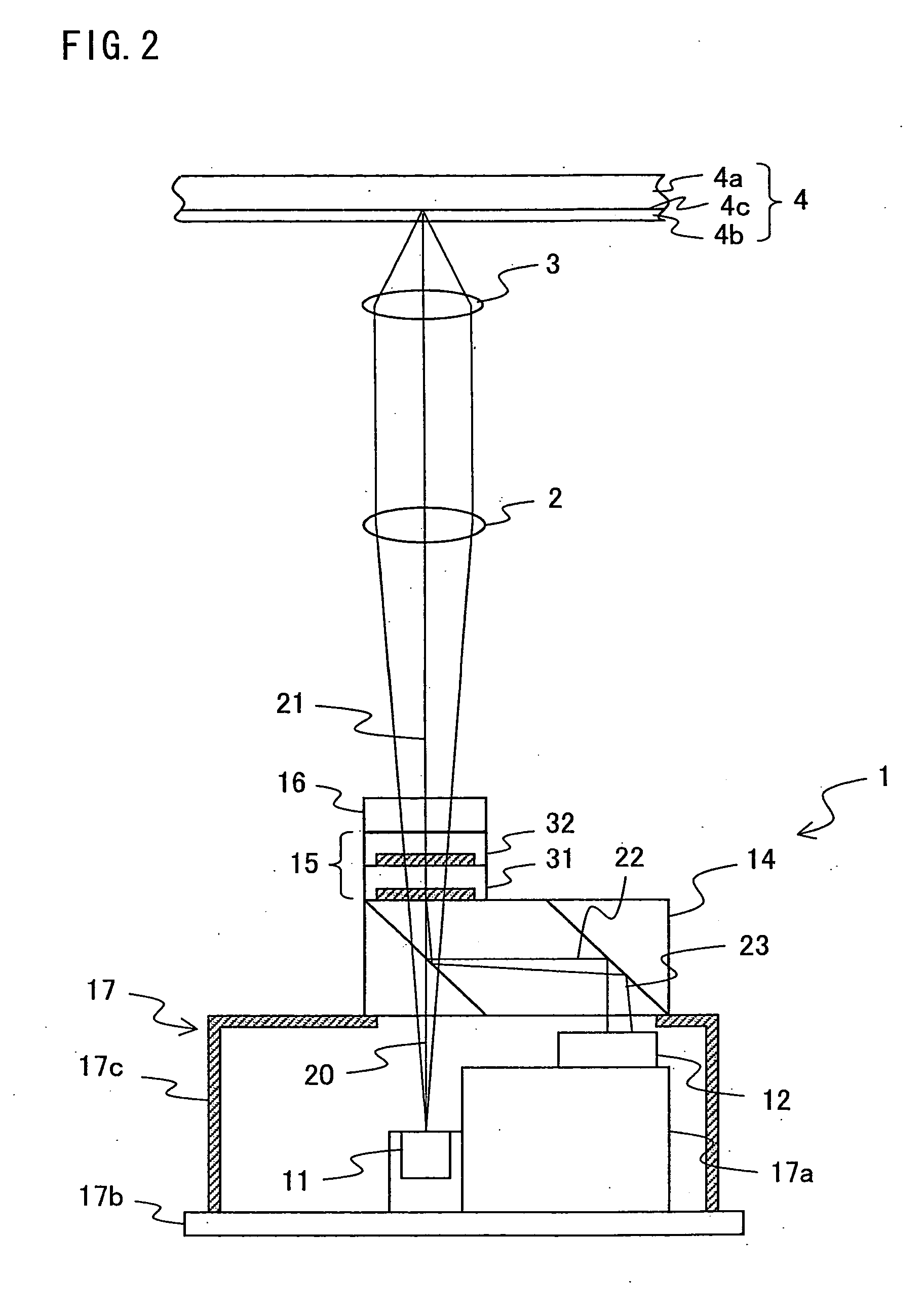
[0056] As illustrated in FIG. 2, an optical pickup device according to the present invention includes an optical integrated unit 1, a collimator lens 2, and an objective lens (converging means) 3. Further, light emitted from the optical integrated unit 1 passes through the collimator lens 2 and the objective lens 3, and then is converged and reflected on an optical disk 4. Moreover, the reflected light passes again through the collimator lens 2 and the objective lens 3, and is converged on a photodetector 12 (described later) in the optical integrated unit 1.

[0057] The optical pickup device according to the present embodiment is arranged such that: the optical integrated unit 1 includes, as a light source, a laser source that projects a light beam having a short wavelength of approximately 405 nm, and the objective lens 3 has a high numerical aperture (NA) of approximately 0.85. T...

second embodiment

[0133] Another embodiment of the present invention will be described below with reference to the drawings. Note that members having the same functions as those described in the first embodiment are given the same reference numerals, and the descriptions thereof are omitted.

[0134] The present embodiment defines a relationship between (i) respective shapes of the main light receiving regions 12i and 12j and the auxiliary light receiving regions 12i′ and 12j′ and (ii) respective shapes of the main light receiving regions 12k and 12l and the auxiliary light receiving regions 12k′ and 12l′. The main light receiving regions 12i and 12j and the auxiliary light receiving regions 12i′ and 12j′ are irradiated with the light beam P1 diffracted by the region 32a of the second polarizing hologram element 32. The light beam P1 includes the optical axis of the light beam projected on the second polarizing hologram element 32. The main light receiving regions 12k and 12l and the auxiliary light re...

third embodiment

[0150] A further embodiment of the present invention will be described below with reference to the drawing. Note that members having the same functions as those described in the first embodiment are given the same reference numerals, and the descriptions thereof are omitted.

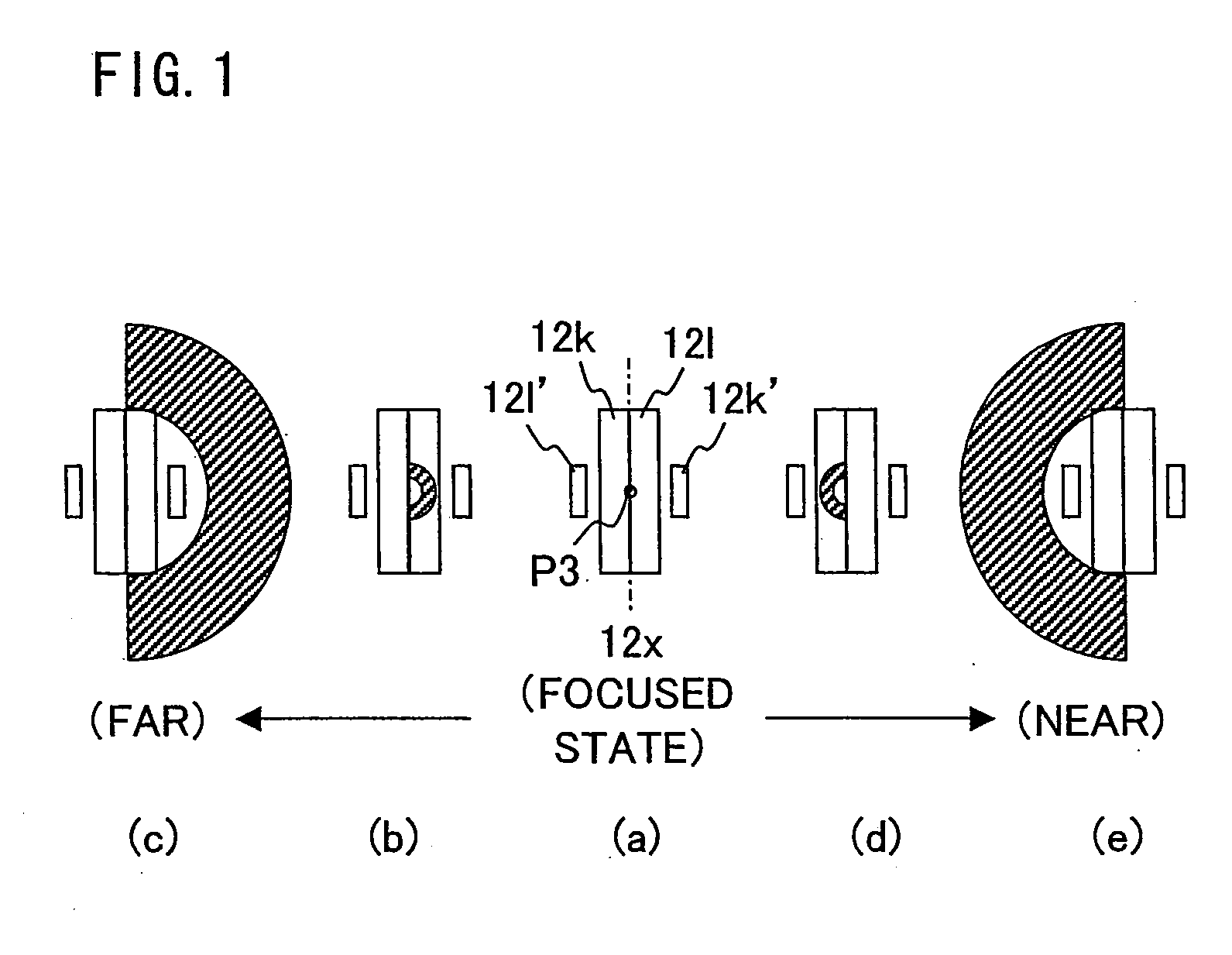
[0151] As described in the first embodiment, the second polarizing hologram element 32 is divided into the three regions 32a, 32b, and 32c. The region 32a diffracts the light beam P1. The region 32c diffracts the light beam P2. The region 32b diffracts the light beam P3. The light beam P1 is projected on the first main light receiving regions 12i and 12j and the first auxiliary light receiving regions 12i′ and 12j′. The light beam P2 is projected on second main light receiving regions 12m and 12n and second auxiliary light receiving regions 12m′ and12n′. The light beam P3 is projected on the main light receiving regions 12k and 12l and the auxiliary light receiving regions 12k′ and 12l′. Described in the present...


PUM


Abstract

An optical pickup device includes: a separation section for separating a light beam into (i) a first light beam, which includes an optical axis of the light beam, and (ii) a second light beam, which surrounds a curved side of the first light beam; and a second light receiving section for receiving the light beam. The second light receiving section includes (I) main light receiving regions, which are provided with a division line therebetween so as to be adjacent to each other and (II) auxiliary light receiving regions, which receive a portion of the light beam which protrudes from each of the main light receiving regions. Each of the auxiliary light receiving regions is positioned in a direction orthogonal to a drawing direction of the division line so as to be adjacent to the main light receiving region. The auxiliary light receiving region is shorter than the main light receiving region in the drawing direction of the division line.

Description

[0001] This Nonprovisional application claims priority under 35 U.S.C. § 119(a) on Patent Application No. 329508 / 2004 filed in Japan on Nov. 12, 2004, the entire contents of which are hereby incorporated by reference. FIELD OF THE INVENTION [0002] The present invention relates to an optical pickup device mounted in an optical disk apparatus for optically recording or reproducing information with respect to an information storage medium such as an optical disk. More particularly, the present invention relates to an optical pickup device capable of performing accurate recording / reproducing operation with respect to an optical disk having a plurality of recording / reproducing layers. BACKGROUND OF THE INVENTION [0003] In recent years, there has been the increasing use of optical disks in various fields such as audiovisual apparatuses, videos, and computers. This is because the optical disks are capable of recording a large quantity of information signals at high density. Recently, there...

Claims


Application Information

Patent Timeline
Patent Type & Authority Applications(United States)
IPC IPC(8): G02B27/40G02B27/64
CPCG11B7/0948G11B7/131G11B7/1353G11B7/1381G11B7/13927G11B7/1395G11B2007/0013
Inventor HORIYAMA, MAKOTO
Owner SHARP KK
Why Eureka
Try Eureka