
Variable diameter cutting tool

a cutting tool and variable diameter technology, applied in the field of rotary cutting tools, can solve the problems of high tooth-count end mills, surface feed marks, and time-consuming hand-finishing operations, and achieve the effects of facilitating machining of metallic and nonmetallic work pieces, reducing or eliminating surface feed marks, and reducing the formation of surface feed marks

Active Publication Date: 2009-12-24
THE BOEING CO
View PDF32 Cites 14 Cited by
  • Summary
  • Abstract
  • Description
  • Claims
  • Application Information

AI Technical Summary

Benefits of technology

[0015]Each of the teeth in the first tooth sections are preferably formed at equal radii. Likewise, each of the teeth in the second tooth sections are preferably formed at equal radii. However, the teeth in the second tooth sections are preferably formed at a reduced radius relative to the radius of the teeth in the first tooth sections so as to minimize or eliminate the formation of surface feed marks generated in high tooth-count cutting tools.
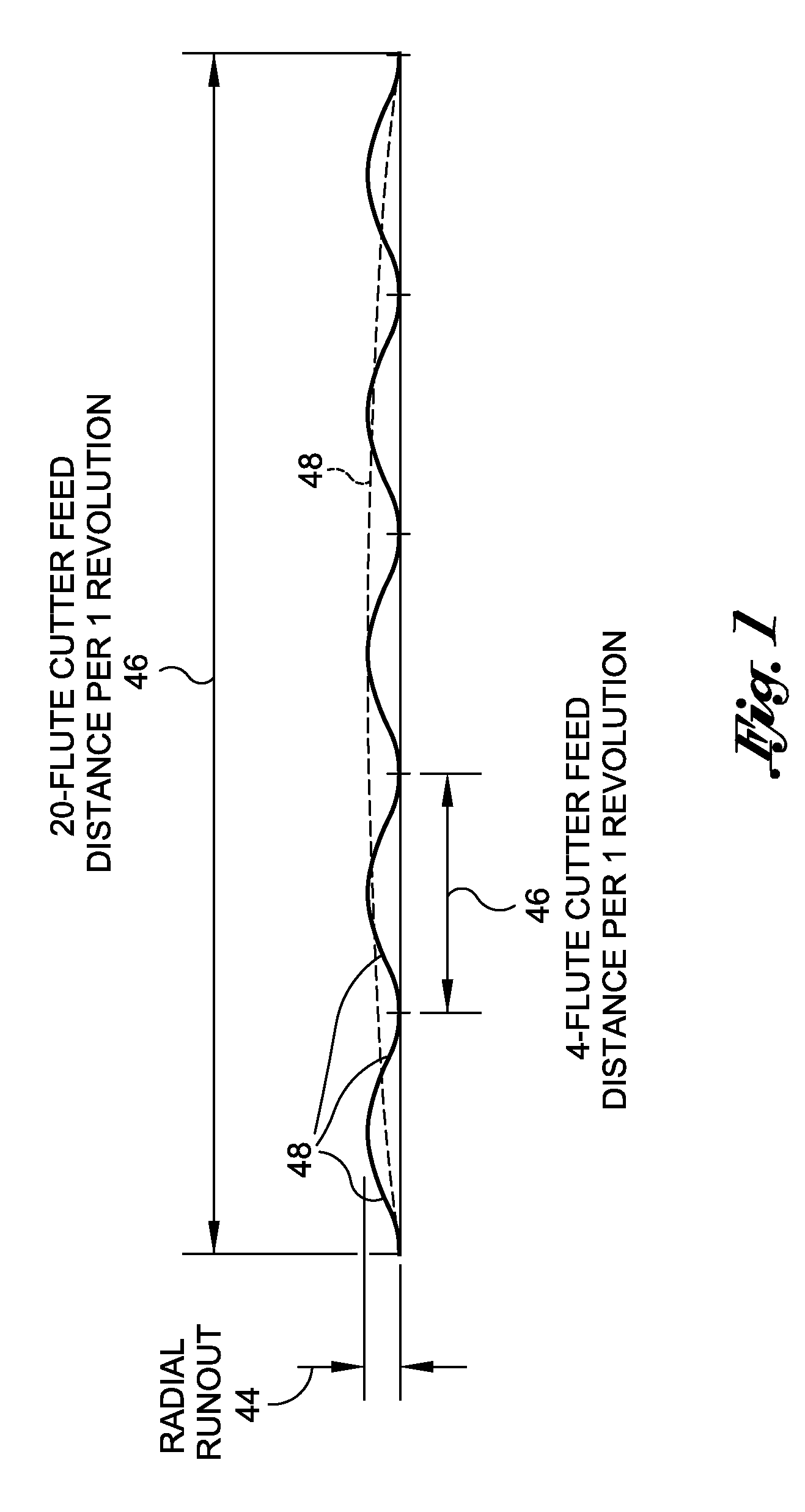
[0016]The technical effects achieved by the disclosure as described herein is a breaking up of surface feed marks normally associated with a high inch-per-revolution feed rate. In this regard, the cutting tool or end mill as disclosed herein facilitates machining of metallic and nonmetallic work pieces at a relatively fast rate but without the associated feed marks. As is known in the art, such feed marks may require post-processing such as hand blending of the work piece.
[0017]In one embodiment, the cutting tool or end mill as disclosed herein may provide for very high feed rates such as greater than 100 inches per minute (IPM) when machining relatively hard materials such as titanium. In this regard, the cutting tool or end mill is configured such that the cutting edges of the teeth in each of the first and second or more tooth sections may dominate the radial runout of the cutting tool.
[0018]In one embodiment, the cutting tool or end mill may comprise a cylindrical or elongate tool body having opposing proximal and distal ends and defining a central axis extending along a length thereof. The tool body may be further divided into a shank portion disposed adjacent to the proximal end and a fluted portion disposed adjacent to the distal end. The shank portion is preferably configured to be engageable to and rotatably driven by a rotary milling machine. In this regard, the shank portion may include surface geometry or surface features which facilitate engagement of the tool body to the rotary milling machine such as via a collet of a spindle.

Problems solved by technology

Unfortunately, although increased feed rates are possible, several disadvantages are associated with high tooth-count end mills.
Radial runout may result in the formation of surface feed marks as the end mill is driven through the work piece.
Such surface feed marks may appear in machined surfaces as peaks and valleys or scallops and may require time-consuming hand-finishing operations in order to smooth out the feed marks.
Unfortunately, the use of low tooth-count end mills results in the production of machined parts at a much slower rate than would be achievable using end mills having a high tooth-count.

Method used


Image

  • Variable diameter cutting tool
  • Variable diameter cutting tool
  • Variable diameter cutting tool

Examples


Embodiment Construction

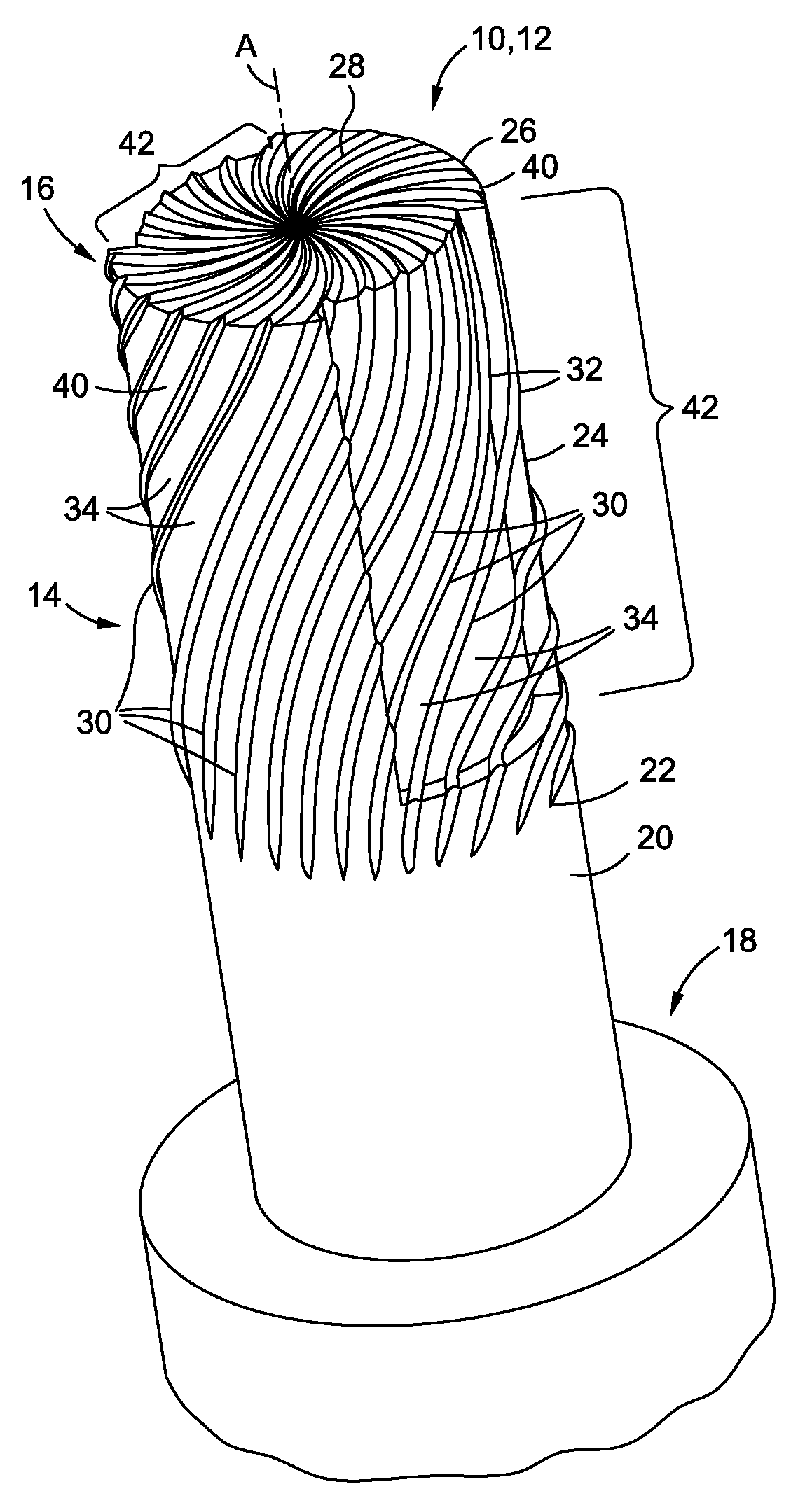
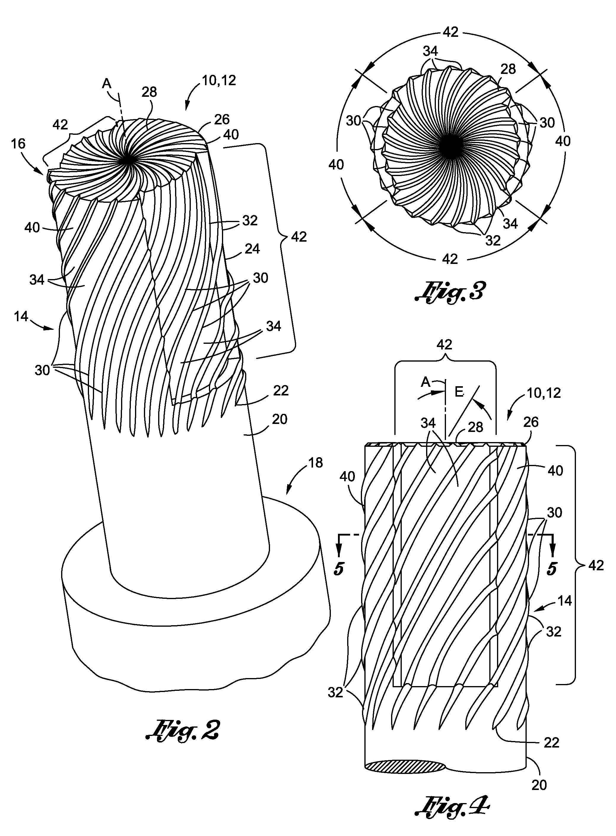
[0035]Referring now to the drawings wherein the showings are for purposes of illustrating preferred and various embodiments of the disclosure only and not for purposes of limiting the same, FIG. 2 is a perspective illustration of a cutting tool 10 or end mill 12, as such terms are used interchangeably throughout this disclosure, and which may be used in various embodiments, methods, apparatuses and systems for minimizing or preventing the occurrence of surface feed marks typically associated with high tooth-count rotary cutting tools. In this regard, the cutting tool 10 and / or end mill 12 as disclosed herein is formed with teeth 30 of varying radii in order to facilitate machining of metallic and / or nonmetallic work pieces at relatively high feed rates without the occurrence of feed marks and thereby avoiding the need for post-machining operations such as hand finishing.

[0036]Referring to FIGS. 2-4, the cutting tool 10, in one embodiment, may include a generally cylindrical elongate...


PUM

PropertyMeasurementUnit
feed distanceaaaaaaaaaa

Abstract

A cutting tool comprises a tool body having proximal and distal ends and defining a central axis. The tool body includes a shank portion and a fluted portion. The shank portion may be configured to be rotatably engageable to a milling machine. The fluted portion may include a plurality of teeth disposed about a circumference thereof and being formed at a radius relative to the central axis. In one embodiment, the teeth may be divided into first and second tooth sections with the teeth in the second tooth section being formed at a reduced radius relative to the teeth in the first tooth section.

Description

CROSS-REFERENCE TO RELATED APPLICATIONS[0001](Not Applicable)STATEMENT RE: FEDERALLY SPONSORED RESEARCH / DEVELOPMENT[0002](Not Applicable)FIELD[0003]The present invention relates generally to rotary cutting tools and, more particularly, to a cutting tool or end mill having teeth of varying teeth radii in order to reduce or prevent surface feed marks normally associated with high feed rates.BACKGROUND[0004]End mills are commonly-used cutting tools for machining work pieces and are typically engaged to a rotary turning machine such as a milling machine. The milling machine rotatably drives the end mill to shape the work piece. End mills are typically provided as elongate, cylindrically shaped elements and may include anywhere from 2 to 20 or more teeth or flutes that are formed on an outer perimeter of the end mill. As distinguished from drill bits which are typically used for forming holes in an axial direction, end mills can be used for shaping work pieces in all directions including...

Claims


Application Information

Patent Timeline
Patent Type & Authority Applications(United States)
IPC IPC(8): B26D1/12B26D1/00B23P17/00
CPCB23C5/10B23C2210/285Y10T407/1962Y10T407/1948Y10T407/1958Y10T29/49
Inventor HANKS, RYAN L.STERN, ERIC J.BOLIN, JARED L.
Owner THE BOEING CO
Learn More