
Cellular communication system and method of operation therefor

a communication system and cellular communication technology, applied in the field of cellular communication systems, can solve the problems of unsuitable dynamically and automatically adapting to changes in cell configuration and layout, inflexible central neighbour list control and management system, cumbersome current approaches, etc., and achieves the effect of facilitating operation, facilitating implementation and improving performance in a cellular communication system

Inactive Publication Date: 2009-12-24
GOOGLE TECH HLDG LLC
View PDF4 Cites 50 Cited by
  • Summary
  • Abstract
  • Description
  • Claims
  • Application Information

AI Technical Summary

Benefits of technology

[0014]The invention may allow facilitated implementation and / or facilitated operation and / or improved performance in a cellular communication system. In particular, improved information of a cell configuration may be determined at a base station. Specifically, information may be obtained directly from the user equipment for not only cells that are cell switch candidates of the base station but also of cells / base stations that are themselves cell switch candidates of these. E.g. information may not only be obtained for neighbour cells but also for neighbour cells of neighbour cells. The approach may for example allow improved and / or facilitated discovery of possible handover or reselection targets for user equipments of different cells. The approach may in particular in many embodiments allow discovery and cell layout / configuration data to be communicated across different cell switch candidate management domains and may in particular facilitate and / or improve distribution of cell layout / configuration information across different communication systems. The approach may in particular facilitate and / or enable distribution and generation of cell relationship data which is useful for generating and / or updating cell switch candidate lists, such as neighbour lists. A cell switch candidate list for a base station may comprise a list of other cells which are potential handover or cell reselection targets for user equipments currently supported by the base station (e.g. in active or idle mode). The improved distribution of information may allow improved cell switch candidate lists resulting in improved cell switch operation for user equipments and thus improved performance of the communication system as a whole.

Problems solved by technology

However, such an approach results in a relatively complex centralised neighbour list control and management system.
However, the current approaches tend to be inflexible, cumbersome, resource demanding and slow.
In particular, the centralised approach of using a common central neighbour list management centre tends to be unsuitable for dynamically and automatically adapting to changed cell configurations and layouts.
In particular, it tends to be impractical for a dynamic and flexible adaptation of neighbour cell lists on an ad-hoc basis.
However, as the different domains may not have information of neighbour cell planning in other parts of the system, it may not be practical or even feasible to use a conventional centralised neighbour list management approach.
Therefore, it may not be practical or feasible to update neighbour lists of one system to reflect the addition or removal of a base station of another system.
In particular, in order to achieve this using a traditional approach, a complex, cumbersome, resource demanding and inflexible interoperation between centralised neighbour list management entities of the different systems is often applied.
Alternatively, intersystem handovers between the systems may be limited.
For example, intersystem handovers may only be possible at the macro-cell layer thereby resulting in a reduced efficiency and suboptimal intersystem handover operation.
Another problem with effective neighbour list management in a dynamic system is that the optimal neighbour lists for the different cells depend on the actual radio environments experienced by the base stations which are typically difficult to determine and evaluate.

Method used


Image

  • Cellular communication system and method of operation therefor
  • Cellular communication system and method of operation therefor
  • Cellular communication system and method of operation therefor

Examples


Embodiment Construction

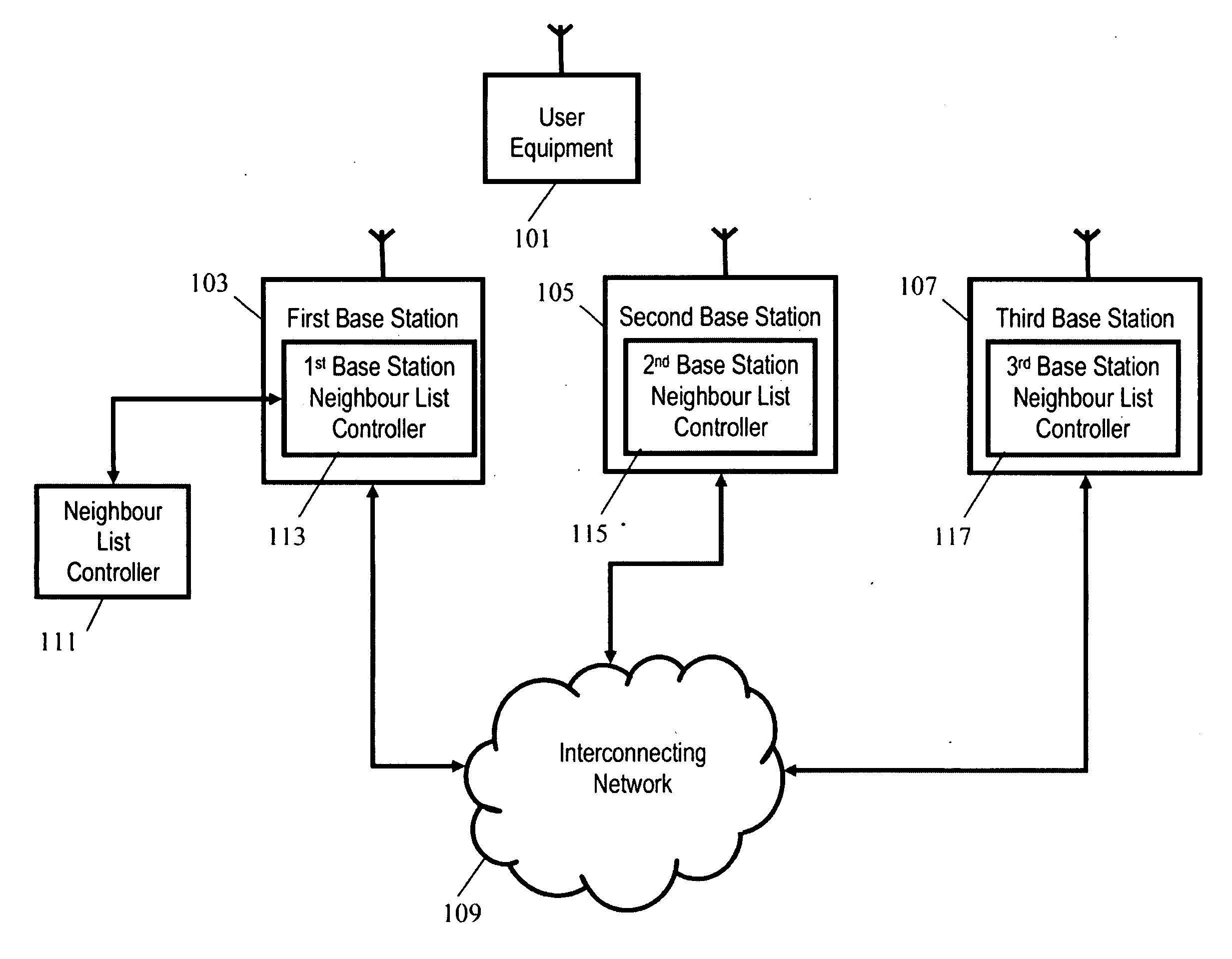
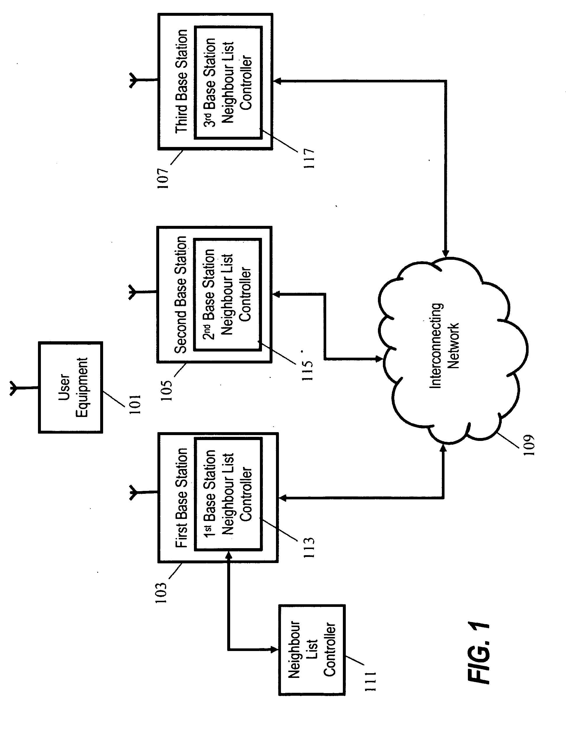
[0022]FIG. 1 illustrates an example of a cellular communication system in accordance with some embodiments of the invention. The cellular communication system is specifically a GSM / UMTS cellular communication system which supports a plurality of user equipments. FIG. 1 illustrates a single user equipment 101 and three base stations 103, 105, 107 which are coupled together via an interconnecting network 109.

[0023]It will be appreciated that for brevity and clarity, FIG. 1 only illustrates components of the cellular communication system required for the following description and that a practical cellular communication system will typically comprise a large number of base stations each capable of supporting a plurality and potentially large number of user equipments. It will furthermore be appreciated that the interconnecting network 101 represents all other aspects of the fixed segment of the GSM / UMTS communication system including other base stations, Radio Network Controllers RNCs),...


PUM


Abstract

A cellular communication system comprises a first base station (103) supporting user equipments (101) in a first cell. A user equipment (101) is supported in the first cell by the first base station (103) and is arranged to transmit previous cell switch candidate data to the first base station (103). The previous cell switch candidate data comprises an indication of at least one cell switch candidate for at least one base station supporting the user equipment prior to the first base station (103). The first base station is arranged to receive the previous cell switch candidate data transmitted from the user equipment (101). The previous cell switch candidate data may be used for different purposes such as synchronization of cells or generation of suitable cell switch candidate lists, such as neighbour cell lists. In particular, the approach may allow an improved automated or semi-automated generation of neighbour cell lists for a dynamically changing cell layout.

Description

FIELD OF THE INVENTION [0001]The invention relates to a cellular communication system and a method of operation therefor and in particular, but not exclusively, to a heterogeneous cellular communication system.BACKGROUND OF THE INVENTION [0002]Cellular communication systems including 2nd and 3rd generation cellular communication systems, such as the Global System for Mobile communication (GSM) and the Universal Mobile Telecommunication System (UMTS), as well as wireless area networks such as IEEE 802.xx systems (including Wireless Local Area Networks (WLANs), Wireless Metropolitan Area Networks (WMANs) etc) have become increasingly widespread and popular.[0003]Although many cellular systems were originally designed as single stand alone systems with well defined components, network architectures, data protocols and communication services, there is an increasing tendency to integrate and combine different systems and communication services. For example, there is an increasing focus o...

Claims


Application Information

Patent Timeline
IPC IPC(8): H04W48/20H04W36/00
CPCH04W48/20H04W36/00
Inventor THOMAS, HOWARD J.FOSTER, GERARD T.
Owner GOOGLE TECH HLDG LLC
Learn More