

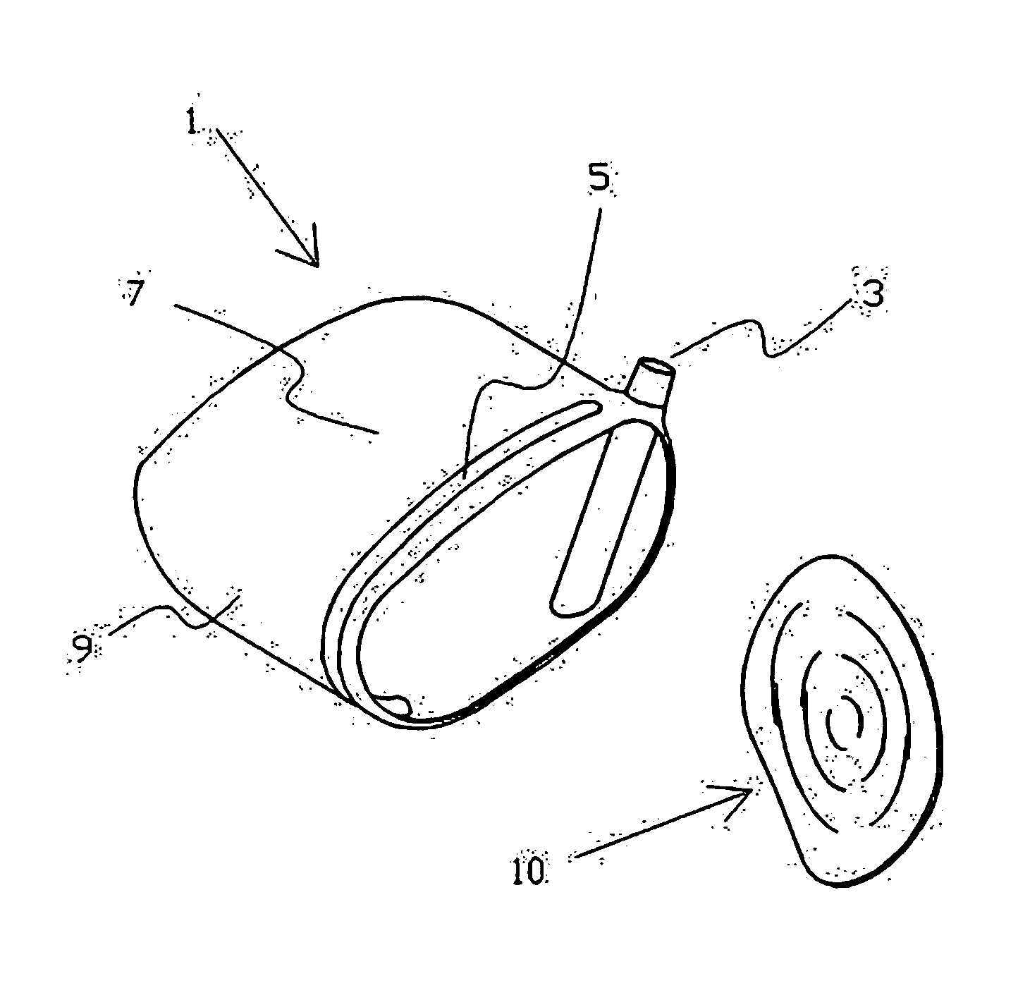
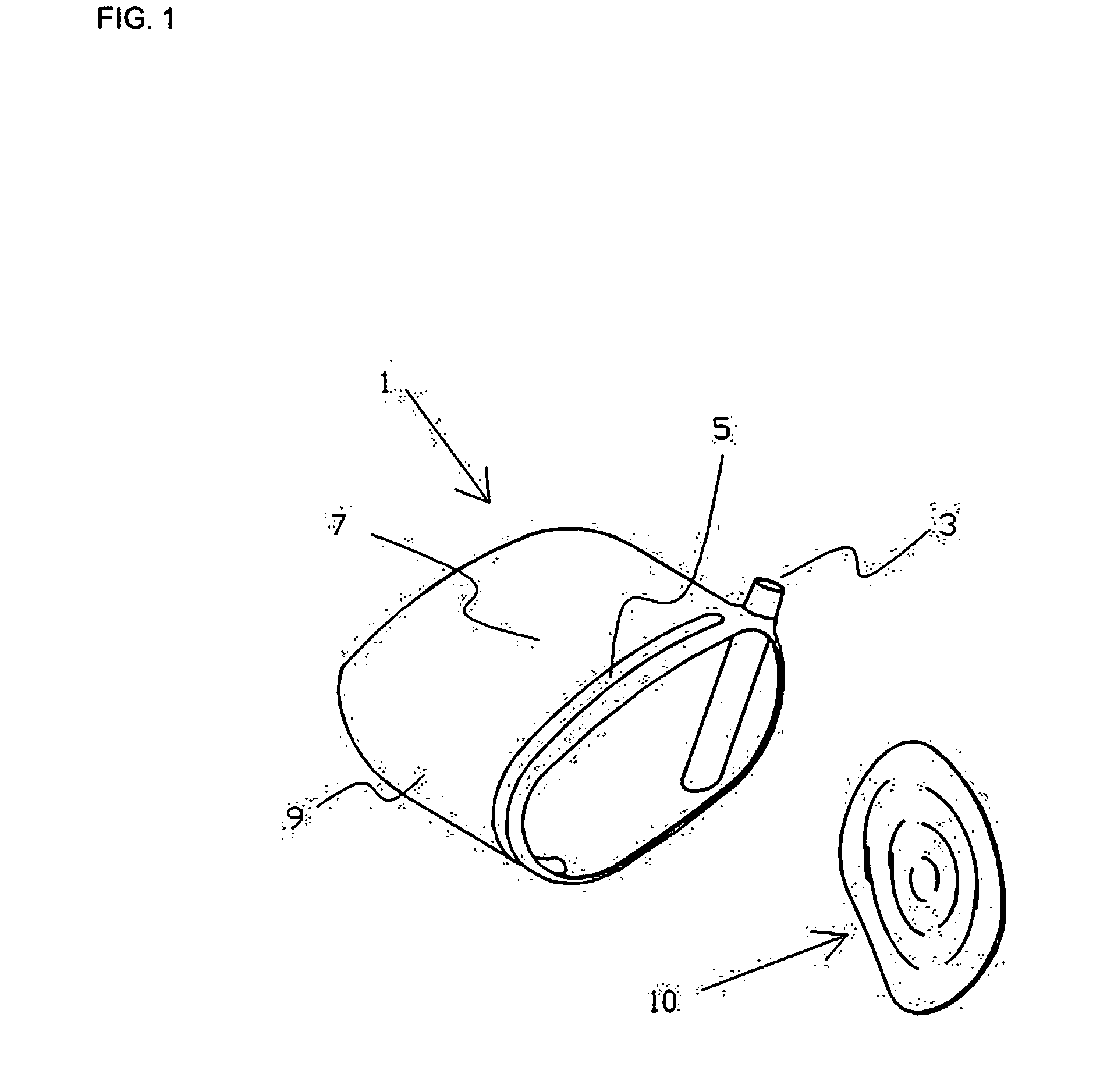
Golf Club Head with Ripple Structure
a golf club and ripple technology, applied in the field of golf clubs, can solve the problems of low peak stress, club head face or adjacent area can crack, etc., and achieve the effects of improving the resistance power, reducing the brakeage rate of the driver head, and raising the maximum impact strength
- Summary
- Abstract
- Description
- Claims
- Application Information
AI Technical Summary
Benefits of technology
Problems solved by technology
Method used
Image

Examples
second embodiment
DESCRIPTION OF INVENTION
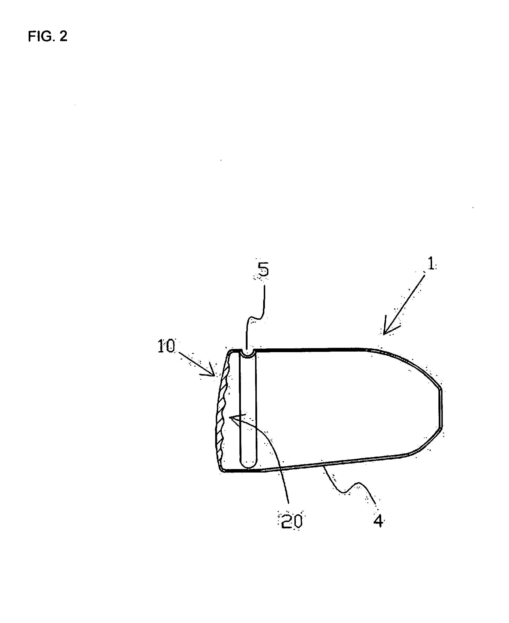
[0024]As illustrated in FIGS. 5 & 6, the second embodiment of this invention has a spiral shaped series of peaks. First peak 30 starts at the center of the inner surface of the face plate 20 of hitting area 10 and last peak 31 ends at the peripheral of the inner surface of the face plate of hitting area. Furthermore, the height D30 of the peak 30 is the highest and starts to get gradually lower and connected to the peak 31 which is the lowest part D31 of the line of peaks.
[0025]Similarly the valley 40 at the center of the inner surface 20 is lined smoothly with the valley 41 on the peripheral of the inner face and the thickness D40 of the valley 40 at the center of the inner face 20 is the thickest and the thickness D41 of the valley 41 on the peripheral of the face is the thinnest among The thickness of the valley 40 becomes shallower gradually meeting the valley 41 smoothly where the peak 31 ends.
PUM
 Abstract
Description
Claims
Application Information