Tilt Correction System and Method for Rail Seat Abrasion

a technology of tilt correction and rail seat, which is applied in the direction of distance measurement, instruments, bolts, screws or clips, etc., can solve the problems of affecting the life of the tie, loosening from the rail, and the friction between the ties and rails, and the surface, so as to achieve cost and labor. the effect of high cos

Active Publication Date: 2009-12-24
LORAM TECH INC
View PDF11 Cites 51 Cited by
  • Summary
  • Abstract
  • Description
  • Claims
  • Application Information

AI Technical Summary

Benefits of technology

[0011]By mounting measurement devices on the inspection vehicle that traverses the track, taking precise measurements of the height of the rail and the tie, and adjusting these measurements for any expected tilt encountered, instances of...

Problems solved by technology

Normal railroad traffic causes friction between ties and rails, as well as rails and spikes, bolts, screws, or clips, and the surface under the ties.
Of particular concern is friction at the point where the rail seats against the tie.
Wear at this point, also known as rail seat abrasion, directly impacts the life of the tie by causing it to loosen from the rail.
In spite of the pads used between rails and concrete ties, rail seat abrasion remains a continuing problem with concrete ties.
When the rail seat wears, it affects the amount of tension on the fastener so that the rail mounting force required to firmly affix it to the tie is not achieved.
Should this happen, the rail can slide against the tie, which increases the rate of abr...

Method used


Image

  • Tilt Correction System and Method for Rail Seat Abrasion
  • Tilt Correction System and Method for Rail Seat Abrasion
  • Tilt Correction System and Method for Rail Seat Abrasion

Examples


Embodiment Construction

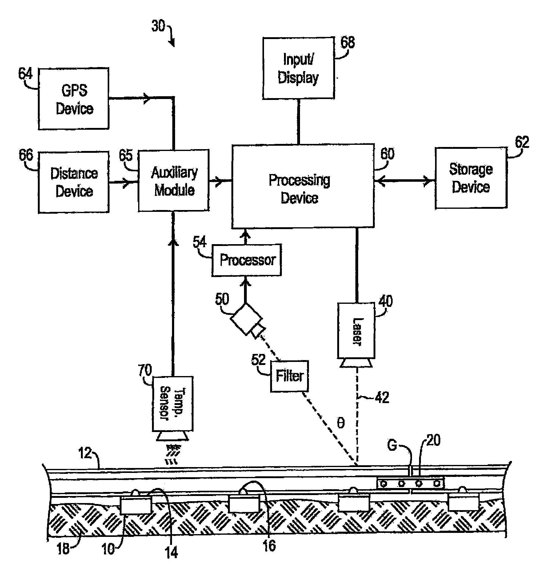
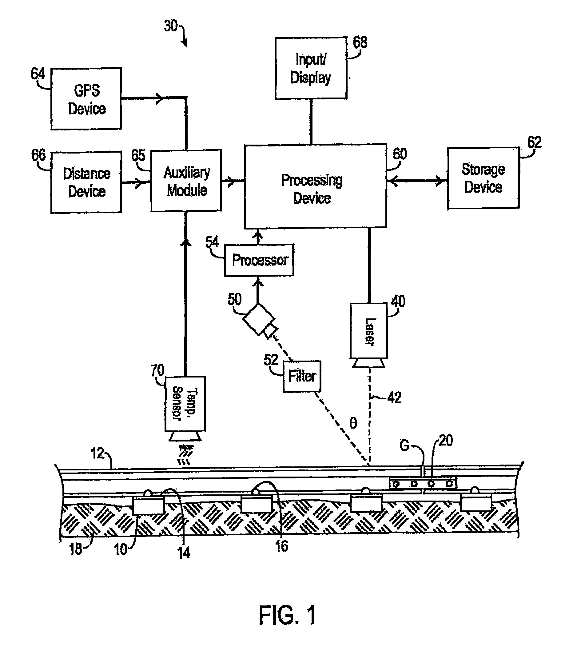
[0031]Referring to FIGS. 1 and 2, an exemplary embodiment of a system 30 for inspecting railroad track according to certain teachings of the present disclosure is illustrated. In FIG. 1, the disclosed inspection system 30 is schematically illustrated relative to a railroad track. In FIG. 2, a portion of the disclosed inspection system 30 is illustrated in a perspective view relative to railroad track.

[0032]As best shown in FIG. 1, the exemplary disclosed inspection system 30 includes a light generator such as a laser 40, a device for receiving light reflected from the area to be inspected such as a camera 50, and a processing device 60. In the implementation shown in FIG. 1, the disclosed inspection system 30 is used to survey the track bed of a railroad track. Although the disclosed inspection system and associated methods are described for use in inspecting railroad track, it will be appreciated with the benefit of the present disclosure that the disclosed system and method can be...


PUM


Abstract

A system and method for determining rail seat abrasion of a rail road track is disclosed. An inspection system comprises lasers, cameras, and processors adapted to determine whether rail seat abrasion is present along the track. The processor employs a mathematics based algorithm which compensates for tilt encountered as the inspection system moves along the track.

Description

CROSS REFERENCE TO RELATED APPLICATIONS[0001]This application is a continuation-in-part of U.S. application Ser. No. 12 / 465,473, entitled, “SYSTEM AND METHOD FOR INSPECTING SURFACES USING OPTICAL WAVELENGTH FILTERING, filed May 13, 2009, naming John Nagle, Steven C. Orrell, Christopher Villar, and Charlie Aaron as inventors, which is a continuation-in-part of U.S. application Ser. No. 11 / 172,618, entitled, “SYSTEM AND METHOD FOR INSPECTING RAILROAD TRACK, filed Jun. 30, 2005 and naming John Nagle, Christopher Villar and Steven Orrell as inventors, which is a non-provisional application claiming benefit of U.S. Provisional Application Ser. No. 60 / 584,769, also entitled, “SYSTEM AND METHOD FOR INSPECTING RAILROAD TRACK, filed Jun. 30, 2004, naming John Nagle and Steven C. Orrell as inventors, each being hereby incorporated by reference in their entirety.FIELD OF THE INVENTION[0002]The present invention relates generally to systems and methods for inspecting railroad surfaces and, more...

Claims


Application Information

Patent Timeline
IPC IPC(8): G06F19/00
CPCG01C3/08B61K9/08B61L23/044B61L23/045
Inventor VILLAR, CHRISTOPHER M.NAGLE, II, JOHN ANTHONTYORRELL, STEVEN C.
Owner LORAM TECH INC
Why Eureka
Try Eureka