
Fueling device

Active Publication Date: 2009-12-31
TOYODA GOSEI CO LTD
View PDF7 Cites 8 Cited by
  • Summary
  • Abstract
  • Description
  • Claims
  • Application Information

AI Technical Summary

Benefits of technology

[0007]An advantage of some aspects of the invention is to provide a highly universal fueling device having minimal flow passage resistance to fuel during fueling, and adaptable for use in vehicles of various types.
[0009]According to the fueling device disclosed in the first mode, if a small pipe is slipped into the fuel passage from the inlet, the tip of the pipe will hit against the grating member which has been provided in the fuel passage, thus preventing the pipe from reaching down the fuel level in the fuel tank. Accordingly, it will not be possible to siphon out fuel from the fuel tank through a pipe, so that theft of fuel can be prevented.
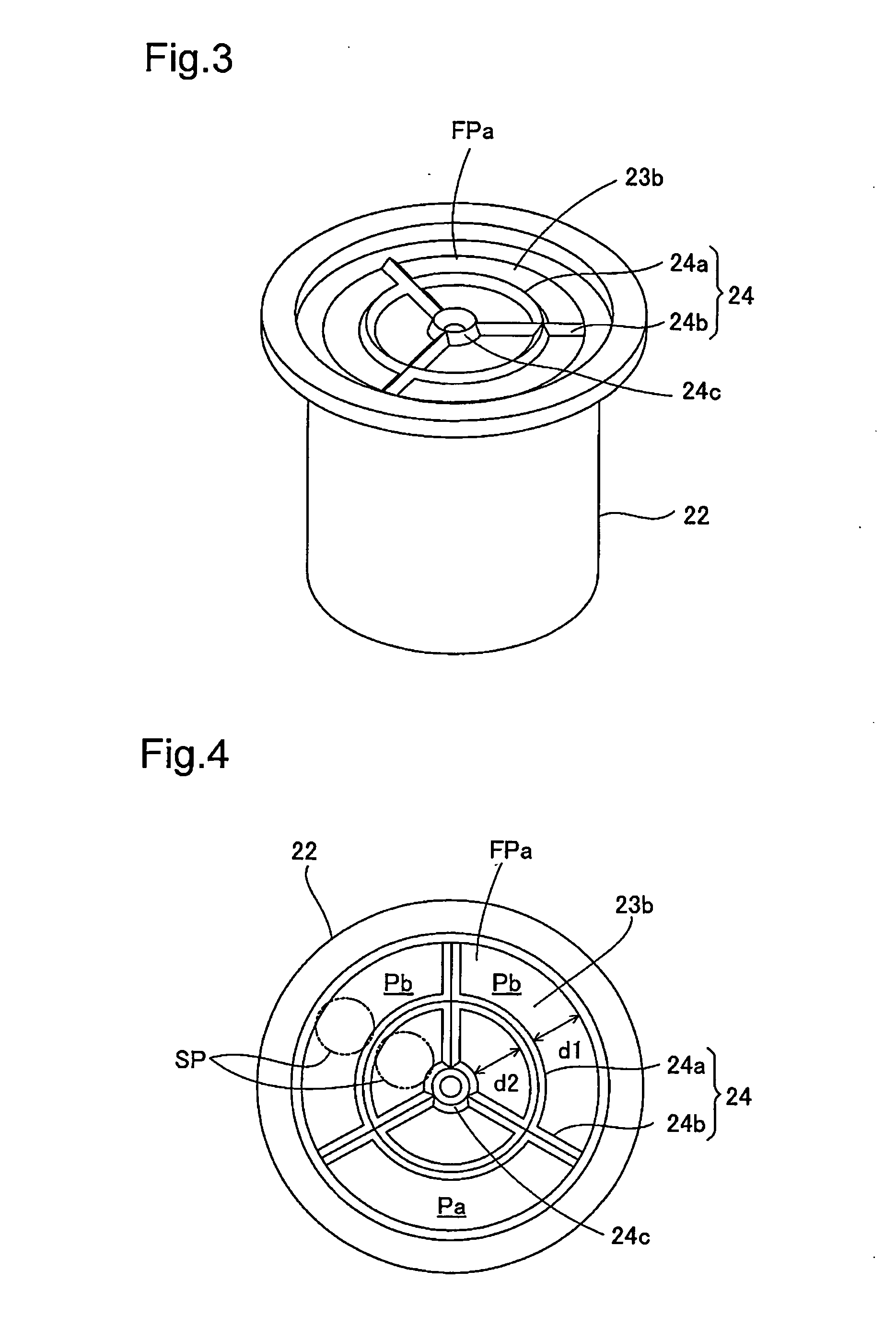
[0010]During fueling, fuel flowing through the fuel passage from the fuel gun will pass through gaps between the annular body and the support body and then flow into the fuel tank. In the design of the grating member, the annular body is principally responsible for the function of restricting insertion of a pipe, while the support body simply serves to support the annular body on the inside wall of the fueling spout. Thus, sections in the support body that extend upright from the inside wall of the fueling spout can be minimized so as to not disturb the initial flow of fuel along the inside wall of the fueling spout, and so as to not give rise to increasing flow passage resistance with subsequent increase of the flow of fuel, thus allowing the fueling operation to proceed unimpaired.
[0011]In a second mode, the support body is situated extending radially from the center of the fuel passage. This arrangement affords larger passage area in the lower part of the fuel passage, and will not lead to increased flow passage resistance by the support body.
[0012]In a third mode, the annular body and the support body have triangular cross section adapted to reduce flow passage resistance to fuel from the inlet towards the fuel tank. This arrangement affords lower flow passage resistance when fuel flowing through the fuel passage collides with the annular body and with the support body of the grating member.

Problems solved by technology

However, increased flow resistance to fuel flowing along the inside wall of the inlet pipe is a problem associated with inlet pipes that are provided with the grating members.
However, where the inlet pipe furnished with the grating member is employed in a vehicle that uses gasoline as fuel, inlet pipe diameter may be larger than needed, or limitations may be imposed on pipe routing arrangements, making such designs unsuited to specifications intended to be used in common for gasoline-powered cars.

Method used


Image

  • Fueling device
  • Fueling device
  • Fueling device

Examples


Embodiment Construction

(1) General Configuration of Fueling Device FD

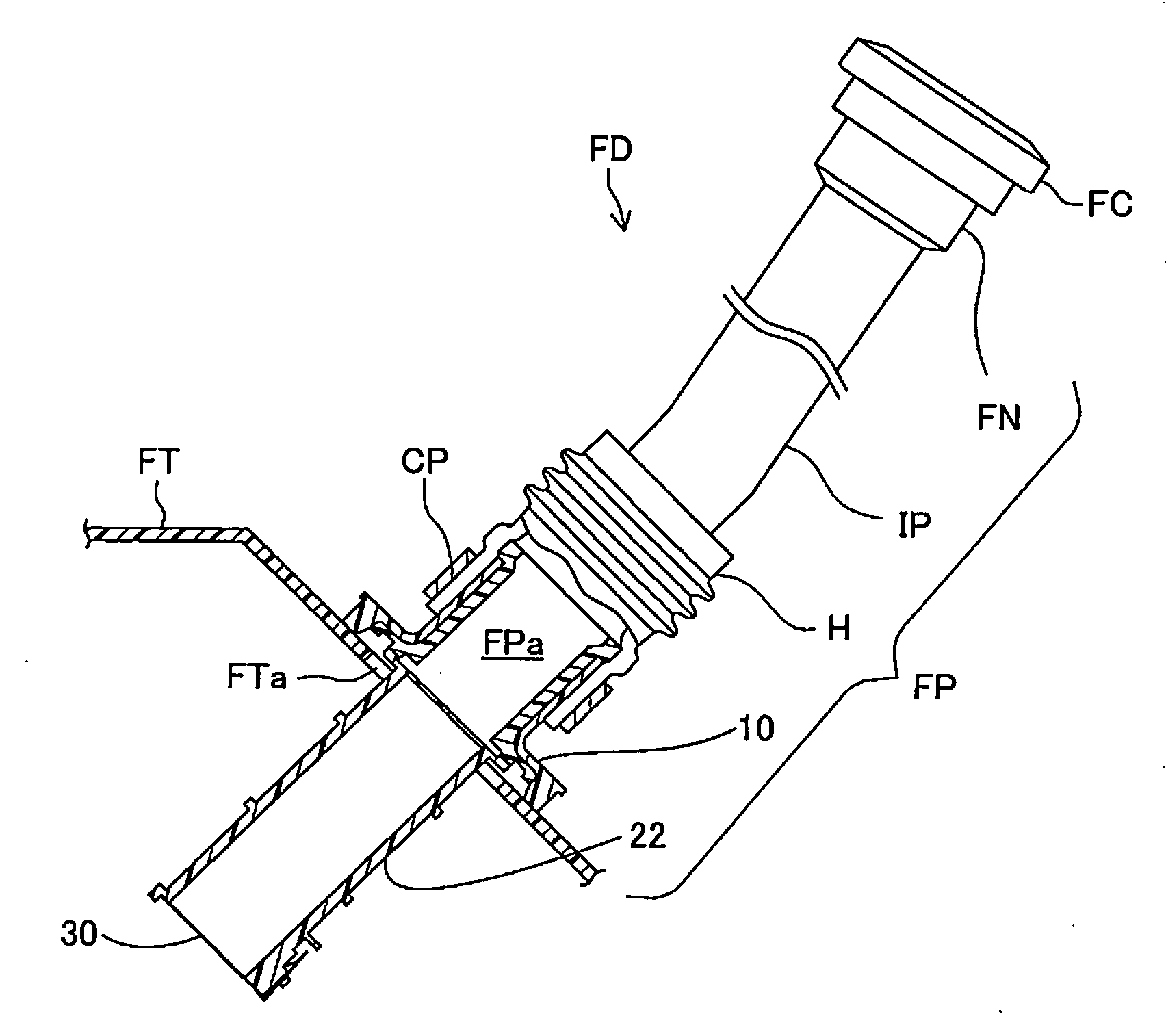
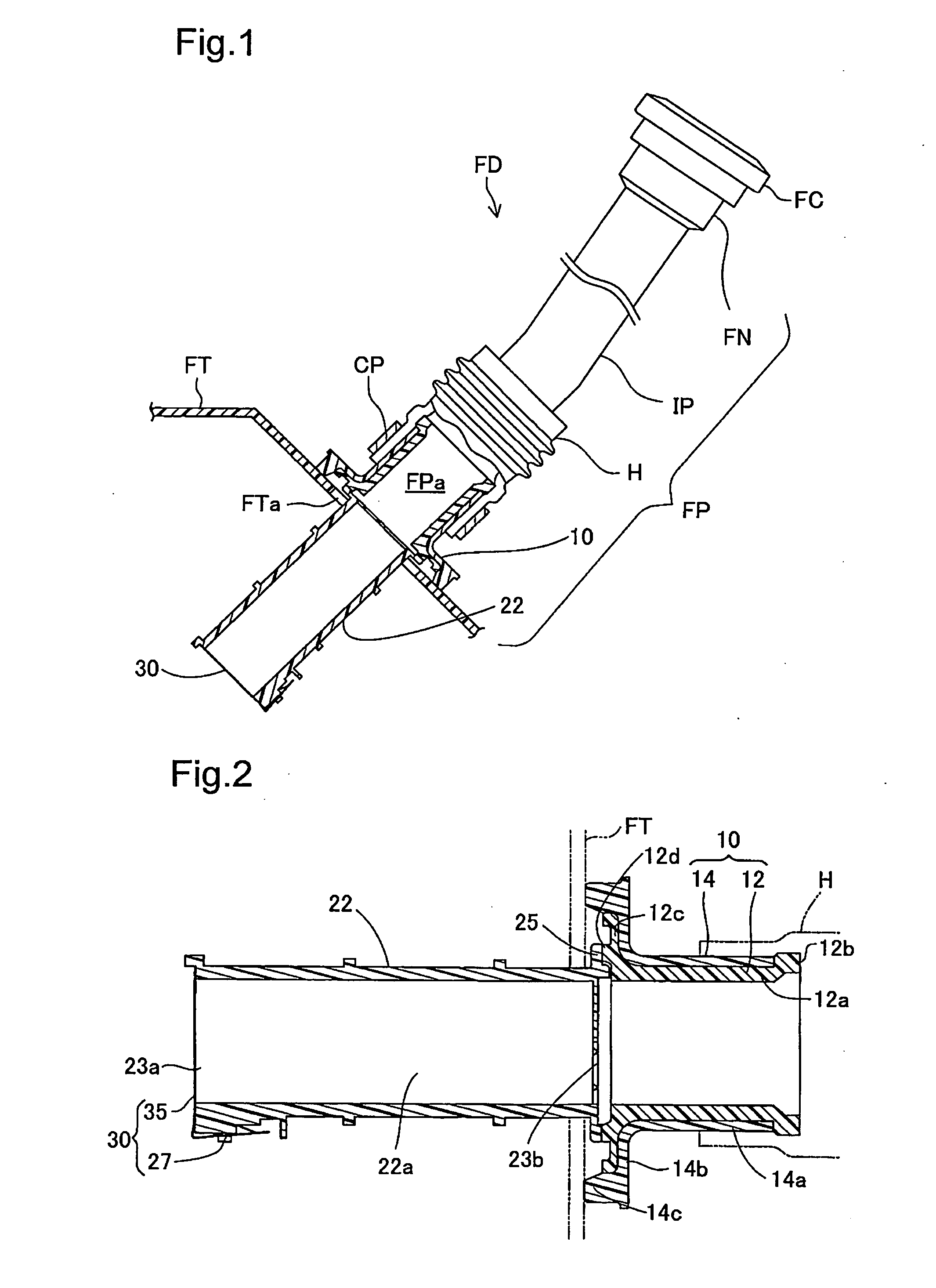
[0023]FIG. 1 is a schematic diagram showing a fueling device FD for supplying fuel to a fuel tank FT of an automobile. As shown in FIG. 1, the fueling device FD is connected to the fuel tank FT, and is adapted to deliver fuel supplied from a fuel gun (not shown) to the fuel tank FT; the system includes a fueling pipe FP that defines a fuel passage FPa leading from the inlet to the fuel tank FT. The fueling pipe FP is furnished with a filler neck FN that has an inlet adapted to be opened or closed by a fuel cap FC; an inlet pipe IP made of metal or resin and connected to one end of the filler neck FN; an inlet hose H connected to the inlet pipe IP; a fuel tank connector 10 that is connected to one end of the inlet hose H and welded to the fuel tank FT; and a passage-defining member 22 that has been welded to the fuel tank connector 10. The inlet hose H is pressure-fit or inserted into the fuel tank connector 10 and is fastened with a clam...


PUM

PropertyMeasurementUnit
Electrical resistanceaaaaaaaaaa

Abstract

The fueling device has a fueling pipe adapted to supply fuel pumped from the inlet opening the fuel tank. A grating member is situated inside the fueling pipe. The grating member includes an annular body positioned substantially concentrically with the fuel passage; and a support body adapted to support the annular body on the inside wall of the flow passage. Gaps present between the inside wall of the passage-defining member and the annular body and the support body constitute part of the fuel passage.

Description

[0001]This application claims the benefit of and priority from Japanese Application No. 2008-168312 filed Jun. 27, 2008, the content of which is incorporated herein by reference.BACKGROUND OF THE INVENTION[0002]1. Field of the Invention[0003]The present invention relates to a fueling device adapted to supply fuel to a fuel tank.[0004]2. Description of the Related Art[0005]In the prior art, it has been known to provide a fuel tank of an automobile with an anti-theft mechanism (JP 11-100060A). The mechanism comprises a grating member with parallel bars adapted to be installed in the fuel passage of the inlet pipe in order to prevent theft of fuel tank from the tank by siphoning it out through a small pipe inserted down through the inlet pipe. In some instances, the anti-theft mechanisms are mandated by law for vehicles that have engines using fuel with alcohol content of 20% or above. However, increased flow resistance to fuel flowing along the inside wall of the inlet pipe is a probl...

Claims


Application Information

Patent Timeline
IPC IPC(8): B65B31/00
CPCB60K15/0403B60K15/04
Inventor ANDO, KOSHISUGIURA, KOJI
Owner TOYODA GOSEI CO LTD
Learn More