Laptop Stand

a technology for laptops and stands, applied in the field of laptop computer stands, can solve the problems of large untapped potential, compromise the safety of laptop computers, lack of substantial support, etc., and achieve the effects of convenient use of the laptop keyboard, low material cost, and convenient assembly and disassembly

Inactive Publication Date: 2009-12-31
PETRIE SCOTT
View PDF35 Cites 30 Cited by
  • Summary
  • Abstract
  • Description
  • Claims
  • Application Information

AI Technical Summary

Benefits of technology

[0017]The EZ Laptop Stand® avoids all of the aforementioned disadvantages while providing a laptop computer stand that also allows a user to comfortably use the onboard keyboard.
[0018]The EZ Laptop Stand® is a laptop computer stand that is very inexpensive, extremely lightweight, easy to assemble and disassemble and folds flat for portability. Although it can be made from any rigid, sheet material, foamcore is the material of choice due to its light weight, inexpensive material cost, and strength and durability when designed in the manner that it is. Manufacturing is done by laser cutting or die cutting, both methods being cost effective and practical for use with foamcore. The main features of the EZ Laptop Stand® consist of one, two or three primary support members, which, when folded at an acute angle and placed on their edge create strong sloped surfaces tapered to a narrower dimension towards the bottom, front edge (the side closest to the user), where feet protrude upward for the laptop computer to rest against. These sloped primary support members are connected by one or two smaller cross-members, also placed on their edge, that slide onto them along interlocking slots thereby forming a rigid, sturdy structure to support a laptop computer, book or other object that a user might want to keep raised off of a work surface or their lap at a forward tilted angle.

Problems solved by technology

In many existing designs or designs for which there are patents, there are multiple features detrimental to their success and in others, the minimization of one detrimental feature is at the maximization of the others to the point where there is not one existing design that has insignificant negative factors.
It is these negative factors that have prevented all predecessors in the laptop stand market from achieving a significant market share, that as a result, has a large untapped potential.
In fact, flexible material used in the construction of the EZ Laptop Stand® would render it unsafe and similarly compromises the safety of the laptop computer stand described in '548.
Also '548 has a limitation in its use, in that it is for supporting a laptop computer only on a flat desktop surface whereas embodiment 3, (model U) of the EZ Laptop Stand® enables it to securely support a laptop computer on a users lap, something that would be precarious with the laptop computer stand described in '548 due to it's construction and shape along the bottom edge of the members.
And in addition to this, even if this main curved member is made as long as it can possibly be, it still lacks substantial support beneath the rear quadrants of any laptop computer, making it far less stable than the design of the EZ Laptop Stand® with it's two (in the preferred embodiments), rigid, folded, sloped primary support members, that securely support any laptop computer at all four main quadrants.
Any material that is flexible does not provide the security needed to safely support any expensive object.
The wide array of laptop computer stands on the market or for which patents have been granted, all have a number of disadvantages inherent in their design that makes them various combinations of too elaborate or too complicated to use, not high enough for proper computer ergonomics, not portable enough, not ventilating enough or too difficult or expensive to manufacture and sell that it is not surprising that none of them have secured a significant share in a market that has significant needs that have not yet been met.

Method used


Image

  • Laptop Stand
  • Laptop Stand
  • Laptop Stand

Examples


embodiment 1

DETAILED DESCRIPTION—ALTERNATIVE EMBODIMENTS TO EMBODIMENT 1

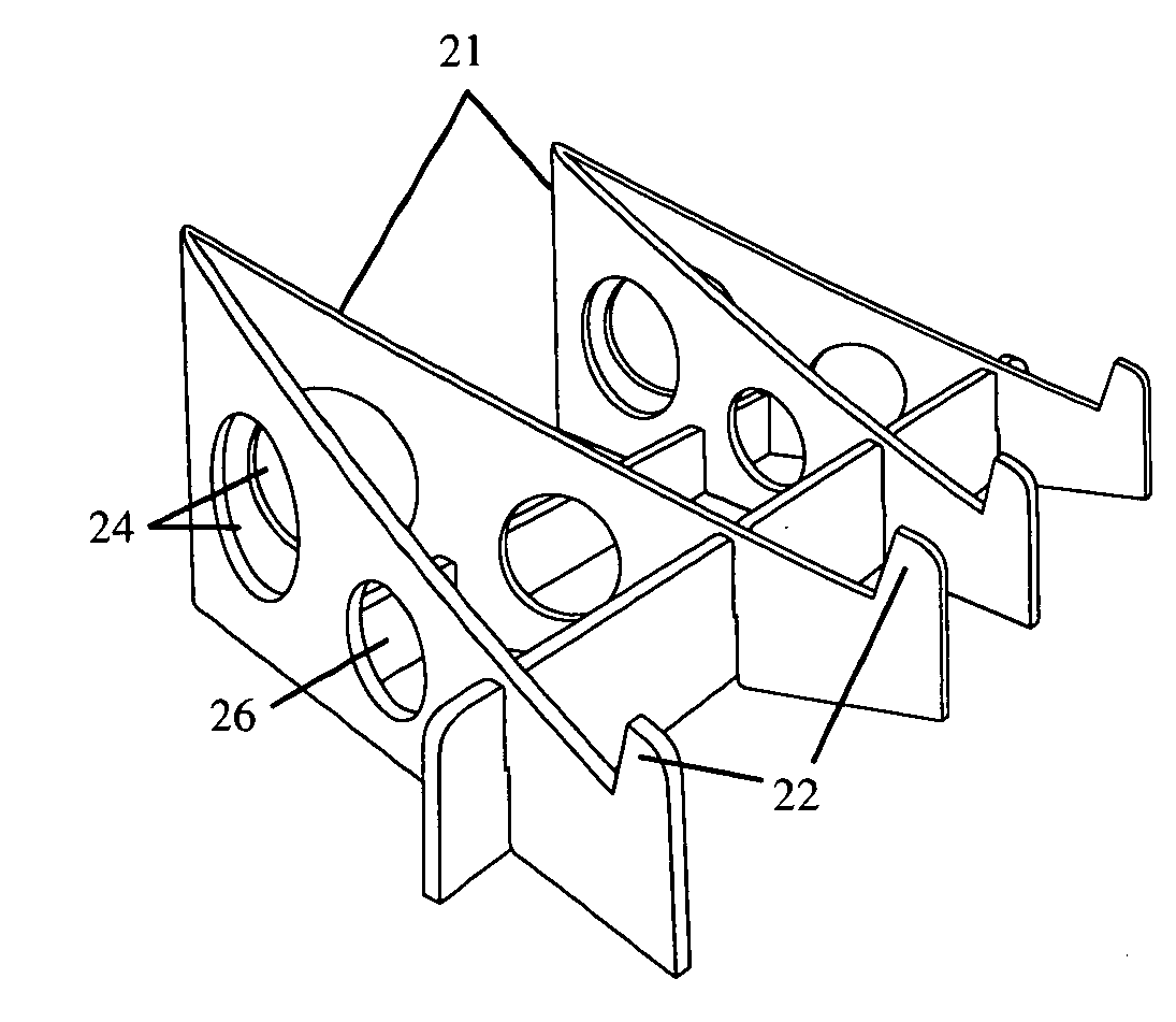
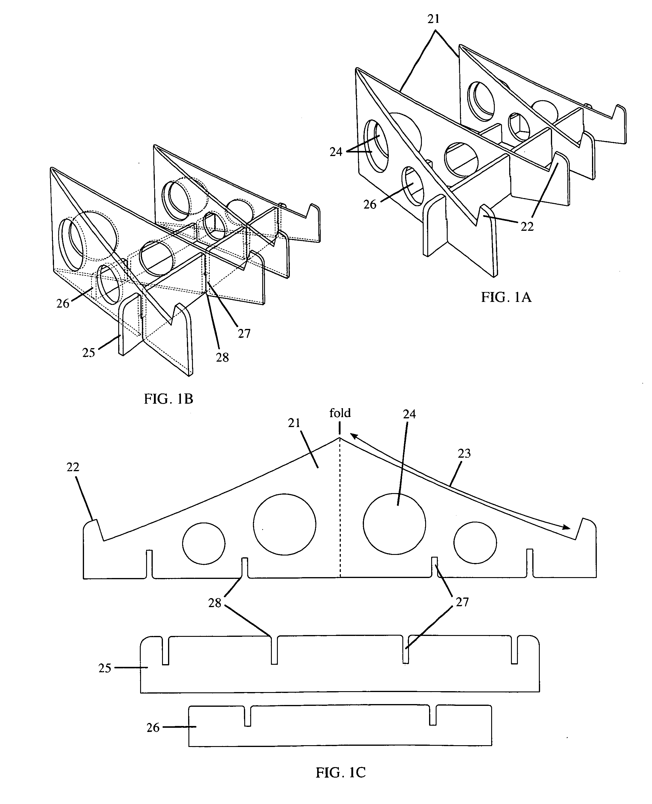
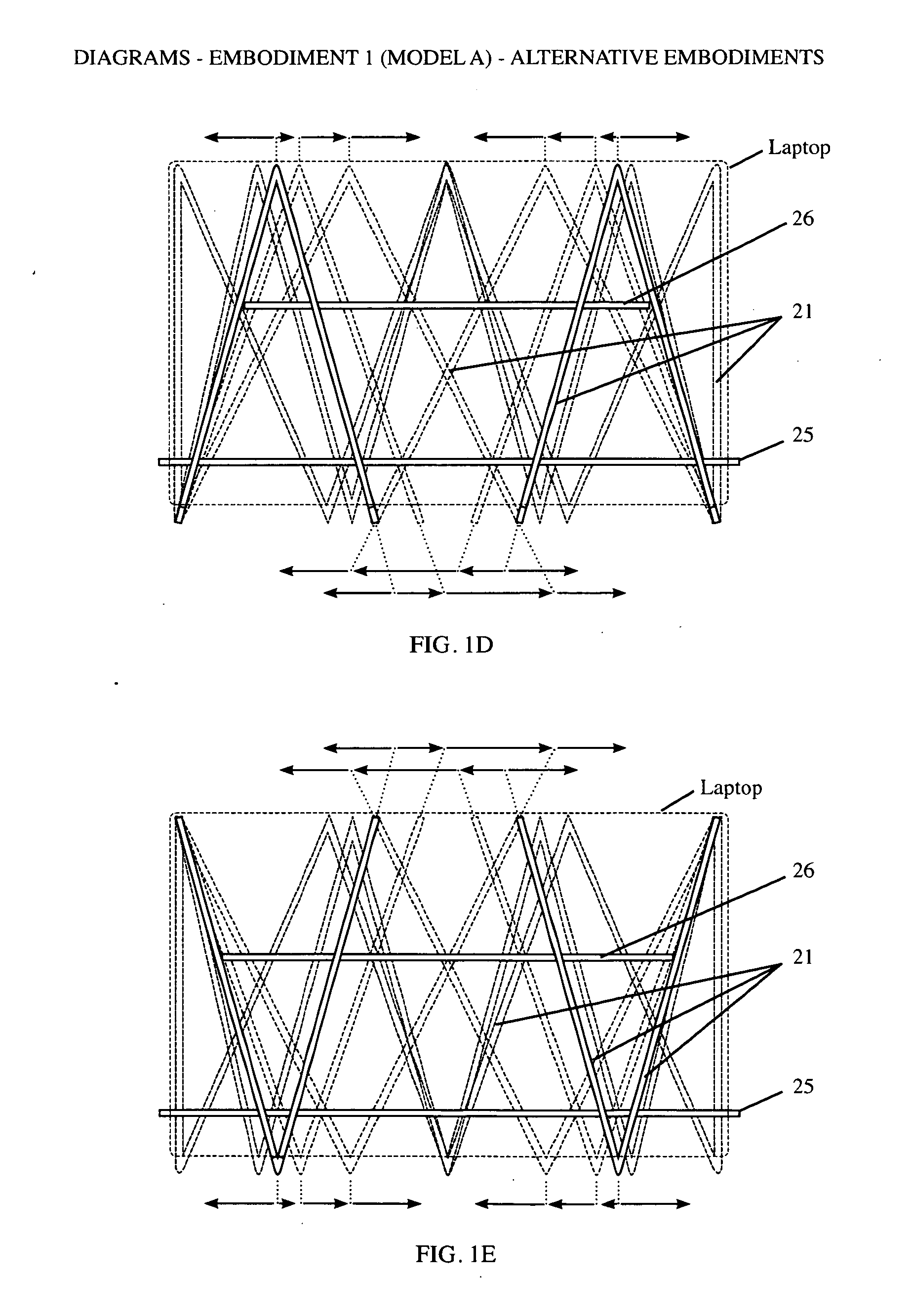
[0051]Alternative embodiments of Embodiment 1 (Model A) can be designed so that the cross-members slide on from the top of the sloped primary support members, instead of the bottom. As shown in FIGS. 1D and 1E, pg. 15, alternative embodiments can also be designed to have a third sloped primary support member in addition to the two shown. This third sloped support member can be designed to be used in an orientation that makes an A-shape or be designed the other way so it makes a V-shape. Alternatively the two sloped primary support members shown in FIGS. 1A, 1B and 1C can be designed to be oriented the opposite way around so they make a V-shape instead of an A-shape, shown in FIG. 1E, pg. 15. Other alternative embodiments are also shown in FIGS. 1D and 1E, where the sloped primary support members are Accordion-shaped, being formed from one long piece with multiple folds in it.

[0052]The dotted lines in FIGS. 1D and 1E show so...

embodiment 2

DETAILED DESCRIPTION—ALTERNATIVE EMBODIMENTS TO EMBODIMENT 2

[0057]Embodiment 2 (Model X) can alternatively be designed to have a second cross member, as an alternative to the one shown, or in addition to it. It will slide onto the bottom edge of the front half of the 2nd primary sloped support member 21 along optional slots 27, FIG. 2C, indicated with dotted lines, instead of the rear half of the 1st primary sloped support member 21 as shown by the slots 27, FIG. 2C, indicated with solid lines. As with the other cross-member it will slide on from below along slots 27 (dotted lines), on FIG. 2C, or as an alternative embodiment, from above, and / or onto both or just one of the sloped members. When sliding onto both sloped members it will be the full width of the EZ Laptop Stand® with four slots in it, looking similar to the front cross-member on Embodiment 1 (Model A). These alternative slots 27, shown with dotted lines on FIG. 2C, will be positioned between the fold and the small hole...

embodiment 13

DETAILED DESCRIPTION—EMBODIMENT 13

[0060]Embodiment 3 of the EZ Laptop Stand (Model U) is illustrated in FIGS. 3A, 3B, 3C, 3D, 3E, 3F, 3G and 3H. The reference numbers used for the parts of this embodiment throughout this description are found on FIGS. 3A, 3B, 3C and 3D on page 18. This embodiment differs from both embodiment 1 (Model A) and embodiment 2 (Model X) in that it is not meant to support a laptop computer on a desk or tabletop surface, but on a users lap while either sitting in a chair or reclining on a bed or couch.

[0061]Embodiment 3 (Model U), like Embodiment 1 (Model A), is comprised of two A-shaped sloped primary support members 21 (or three, A-shaped or V-shaped sloped primary support members in other embodiments). These sloped primary support members differ from those in Embodiment 1 (Model A) by being opposite each other in shape (mirror images of each other) in order to fit the shape of a users lap. The two struts, created when these two A-shaped sloped primary sup...


PUM


Abstract

The EZ Laptop Stand® is a stand for a laptop computer that is very inexpensive, extremely lightweight, easy to assemble and disassemble and folds flat for portability. It is made from foamcore for its light weight, inexpensive material cost, and strength and durability when designed in the manner that it is. Manufacturing is done by laser cutting or die cutting, both methods being cost effective and practical for use with foamcore. There are three models of the EZ Laptop Stand®, the main feature of all three consisting of primary support members, which when folded or hinged at an acute angle at their mid point, create two strong triangular sloped surfaces tapered to a narrower dimension towards the bottom, front edge (the side closest to the user), where feet protrude upward for the laptop computer to rest against. These two primary support members are connected by two smaller cross-members that slide onto them along slots that keep all the pieces of the EZ Laptop Stand® fixed, in a rigid, upright formation on which the laptop computer rests. The EZ Laptop Stand® raises the laptop computer high enough to achieve proper ergonomics for the user while allowing comfortable use of onboard keyboard, high enough to allow adequate ventilation for heat dissipation from under the computer, high enough to provide protection from spilled of beverages, and is inexpensive to buy and simple to disassemble and reassemble for easy portability.
The EZ Laptop Stand® is made in 3 different designs called Model A, Model X, and Model U. Model A and Model X are for use on a desktop surface, under any laptop computer, but each one is designed to better accommodate slightly different configurations of laptop computers. Model U is for using a laptop computer while sitting or lying down when the user wishes to use it directly on their lap.

Description

CROSS-REFERENCE TO RELATED APPLICATIONS [0001]Not ApplicableFEDERALLY SPONSORED RESEARCH [0002]Not ApplicableSEQUENCE LISTING OR PROGRAM [0003]Not ApplicableBACKGROUND [0004]1. Field[0005]This application relates to laptop computer stands which are used to support laptop computers or any electronic device or book that benefits from being held up off of a desk surface or a users lap at a angle facing towards the user.[0006]Since the introduction of the laptop computer, users have had the convenience of having a portable computer that can be carried around, opened and used wherever they want. This however has required the user to rest their laptop computers on either a desk or table surface, or their laps which creates in the user an angle of view that is downward the a degree that causes neck and shoulder strain over extended periods of time. Also the physical dimensions of laptop computers prevent the heat generated from the electronic components from dissipating well enough and hea...

Claims


Application Information

Patent Timeline
Patent Type & Authority Applications(United States)
IPC IPC(8): F16M11/22A47B97/02
CPCF16M13/00F16M11/22F16M11/38
Inventor PETRIE, SCOTT
Owner PETRIE SCOTT
Why Eureka
Try Eureka