Panel Fence System and Method

a panel fence and fence technology, applied in the field of fence systems, can solve the problems of ineffective prevention of attempted breaches of conventional fences, prohibitively expensive construction of alternative conventional fences along significant length boundaries, etc., and achieve the effect of reducing the disadvantages and eliminating the problems of previous fence systems

Inactive Publication Date: 2009-12-31
PAYNE FENCE PRODS
View PDF5 Cites 3 Cited by
  • Summary
  • Abstract
  • Description
  • Claims
  • Application Information

AI Technical Summary

Benefits of technology

[0004]According to embodiments of the present invention, disadvantages and problems associated with previous fence systems may be reduced or eliminated.
[0006]Particular embodiments of the present invention may provide one or more technical advantages. Conventional fences for preventing movement across a particular boundary may include, for example, chain link fencing and barbed wire fencing. Certain individuals attempting to cross the particular boundary may attempt to breach these conventional fences in a number of ways, such as by climbing over the fence, cutting through the fence (e.g., using a saw, axe, or torch), or disassembling one or more exposed fasteners securing portions of the fence. For various reasons, these conventional fences may be ineffective in preventing these attempted breaches. Certain other conventional fences, such as those made of concrete, bricks, and / or stone, may be less susceptible to breach, but these alternative conventional fences may be prohibitively expensive to construct along boundaries of significant length.
[0007]The fence system of the present invention may include a number of panels forming a substantially continuous wall that is less susceptible to breach relative to certain conventional fences. In certain embodiments, the fence system of the present invention may reduce or eliminate hand and foot holds. Thus, the fence system of the present invention may be less susceptible to being breached by an individual attempting to climb over the fence system relative to certain conventional fences. In certain embodiments, the fence system of the present invention provides a substantially continuous wall. Thus, the fence system of the present invention may be less susceptible to being breached by an individual attempting to cut through it (e.g., using a saw, axe, or torch), as compared to certain conventional fences. In certain embodiments, the fence system of the present invention is assembled such that all fasteners are located on one side of the fence system (e.g., the “back side” on which the posts and rails are located). Furthermore, the fence system of the present invention may be oriented such that the back side of the fence system is on the secure side of a boundary other side of the fence system (the “attack side”) is on the non-secure-side of the boundary. Thus, the fence system of the present invention may be assembled and / or repaired from the secure side of the boundary and may be less susceptible to being breached by an individual attempting to disassemble the fence system from the non-secure side of the boundary.
[0008]Additionally, the fence system of the present invention may not be prohibitively expensive to construct along boundaries of significant length. Thus, the fence system of the present invention may potentially be a more cost effective solution for certain applications. Furthermore, the fence system of the present invention may be less susceptible to damage than certain conventional fences (e.g., those made of concrete, bricks, metal, and / or stone), such as damage resulting from high winds and / or soil movement.

Problems solved by technology

For various reasons, these conventional fences may be ineffective in preventing these attempted breaches.
Certain other conventional fences, such as those made of concrete, bricks, and / or stone, may be less susceptible to breach, but these alternative conventional fences may be prohibitively expensive to construct along boundaries of significant length.

Method used


Image

  • Panel Fence System and Method
  • Panel Fence System and Method
  • Panel Fence System and Method

Examples


Embodiment Construction

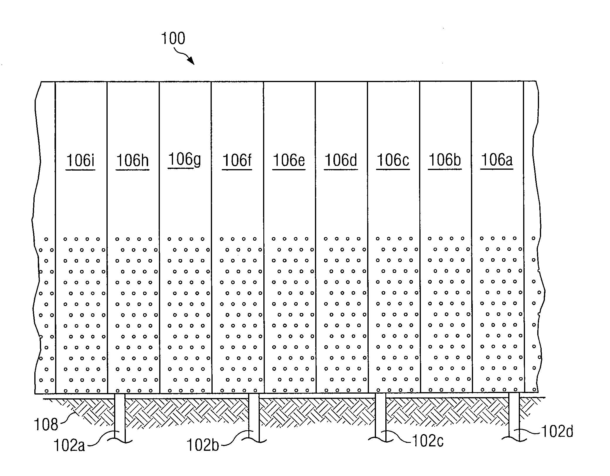
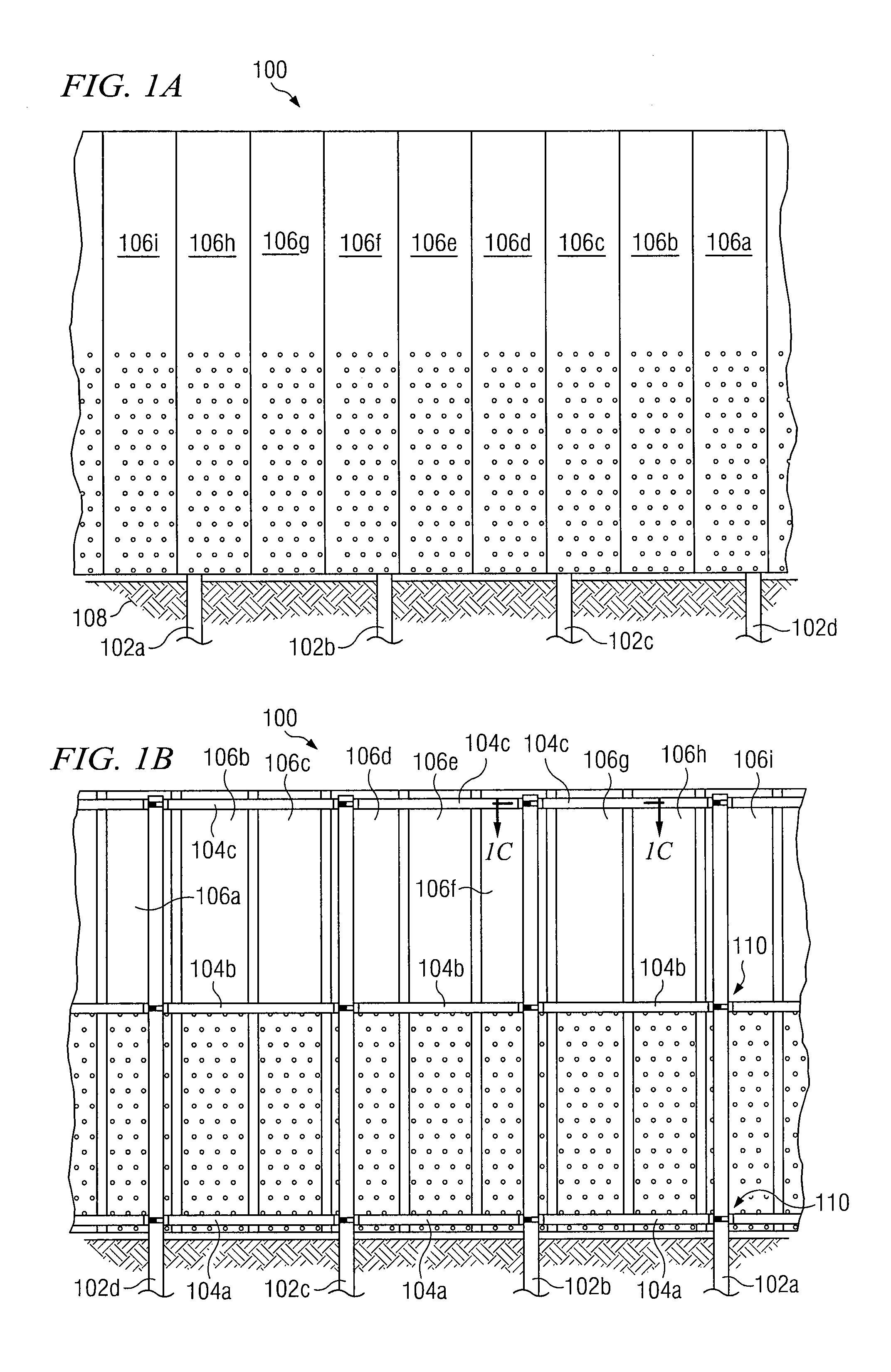
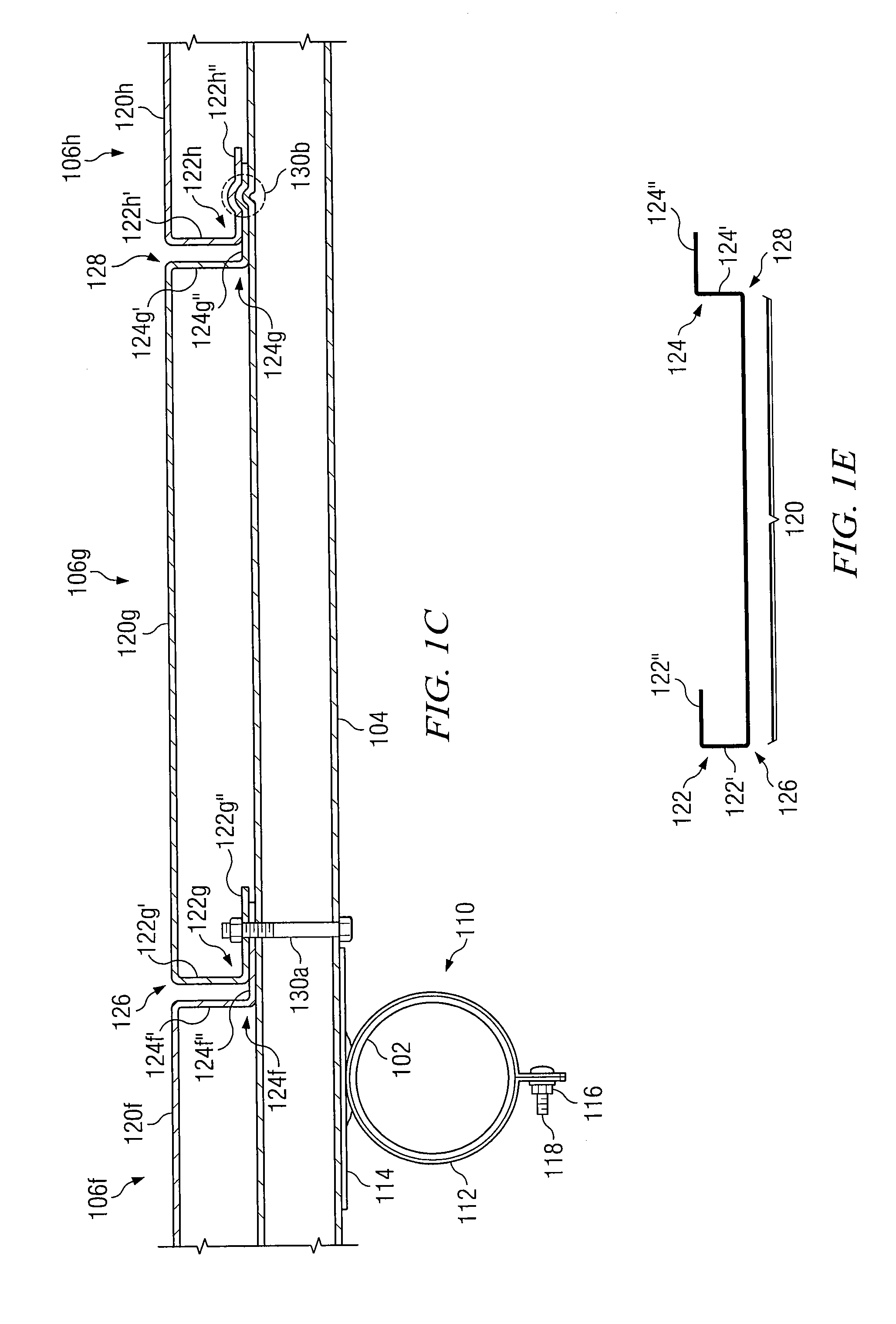
[0016]FIGS. 1A-1E illustrate an example panel fence system 100, according to certain embodiments of the present invention. Fence system 100 may include a number of support members 102 (referred to throughout the remainder of this description as posts 102 for simplicity) and a number of rails 104. Each rail 104 may be attached to at least one post 102 such that the rail 104 extends across the at least one post 102 to which it is attached. Fence system 100 may also include a number of panels 106 each secured to one or more rails 104.

[0017]In general, fence system 100 may deter and / or substantially prevent movement across a particular boundary. Example boundaries include perimeters of critical assets, perimeters of privately-owned real estate, national borders, or any other suitable boundaries. Certain individuals attempting to cross the particular boundary may attempt to breach fence system 100 in a number of ways, such as by climbing over fence system 100, cutting through fence syste...


PUM


Abstract

In certain embodiments, a fence system includes a support member and a rail attached to the support member such that the rail extends across the support member. The fence system further includes a first panel and a second panel each comprising a primary panel portion having a first edge and a second edge. A first flange is located along at least a portion of the first edge of the primary panel portion, and a second flange is located along at least a portion of the second edge of the primary panel portion. The first and second panels are secured to the rail such that the second edge of the primary panel portion of the first panel is adjacent to the first edge of the primary panel portion of the second panel. The second flange of the first panel is matingly coupled to the first flange of the second panel.

Description

RELATED APPLICATIONS[0001]This application claims the benefit under 35 U.S.C. § 119(e) of the priority of U.S. Provisional Application No. 61 / 076,973, filed Jun. 30, 2008, entitled “Metal Panel Fence System, and Method Therefor.”TECHNICAL FIELD[0002]This invention relates generally to fence systems and more particularly to a panel fence system and method.BACKGROUND[0003]It is often desirable or even necessary to prevent people from crossing boundaries, such as a perimeter of privately-owned real estate or another key asset. Free-standing fences may be used to attempt to prevent people from crossing these boundaries. Conventional fences may include, for example, chain link fencing and barbed wire fencing.SUMMARY[0004]According to embodiments of the present invention, disadvantages and problems associated with previous fence systems may be reduced or eliminated.[0005]In certain embodiments, a fence system includes a support member and a rail attached to the support member such that th...

Claims


Application Information

Patent Timeline
Patent Type & Authority Applications(United States)
IPC IPC(8): E04H17/14E04C2/30
CPCE04H17/16
Inventor PAYNE, JOHN F.
Owner PAYNE FENCE PRODS
Why Eureka
Try Eureka