System for turning on and off power using door card key

Inactive Publication Date: 2009-12-31
PARK SE YOUNG
View PDF4 Cites 2 Cited by
  • Summary
  • Abstract
  • Description
  • Claims
  • Application Information

AI Technical Summary

Benefits of technology

[0009]Accordingly, the present invention has been made keeping in mind the above problems occurring in the prior art, and an object of the present invention is to provide a system for turning on and off power using a door card key, which can maintain the state in which one or more electric devices, such as a refrigerator, to which power must be always supplied, are continuously turned on regardless of the entering and leaving of a user even though one or more electric devices are turned on and off depending on whether a door card key is inserted or not.
[0010]Another object of the present invention is to provide a system for turning on and off power using a door card key, in which one or more electric outlets are selectively connected to a door card key receptacle by electric wires, thereby easily performing the construction, maintenance, and management thereof.

Problems solved by technology

However, in the prior art system for turning on and off power using a door card key, since all electric devices are turned on and off depending on whether a door card key is inserted or not, there arises a problem in that electric devices, such as a refrigerator, to which power must always be supplied, are turned on and off based on the entering and leaving of a user.
Further, since all the electric outlets must be connected to a door card key receptacle through electric wires, there is a problem in that it is considerably difficult to construct, maintain, and manage the prior art system for turning on and off power using a door card key.

Method used


Image

  • System for turning on and off power using door card key
  • System for turning on and off power using door card key
  • System for turning on and off power using door card key

Examples


Embodiment Construction

[0016]Reference now should be made to the drawings, in which the same reference numerals are used throughout the different drawings to designate the same or similar components.

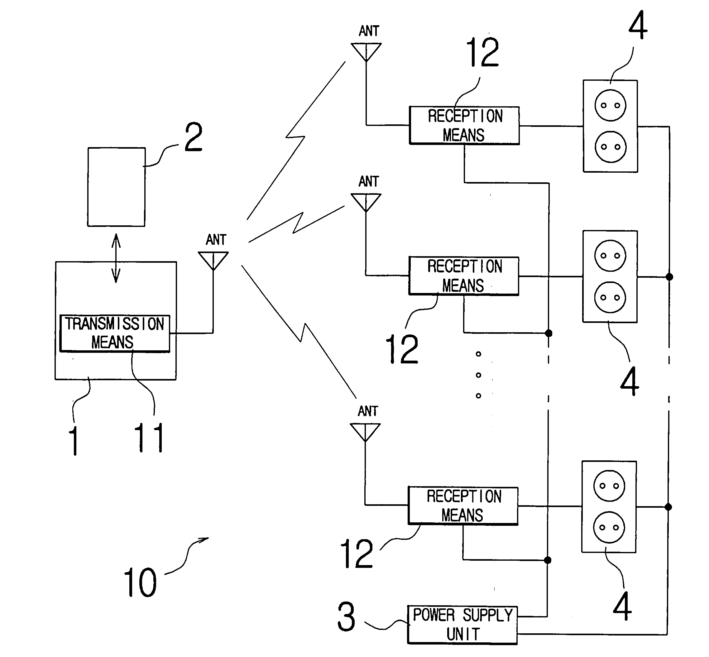
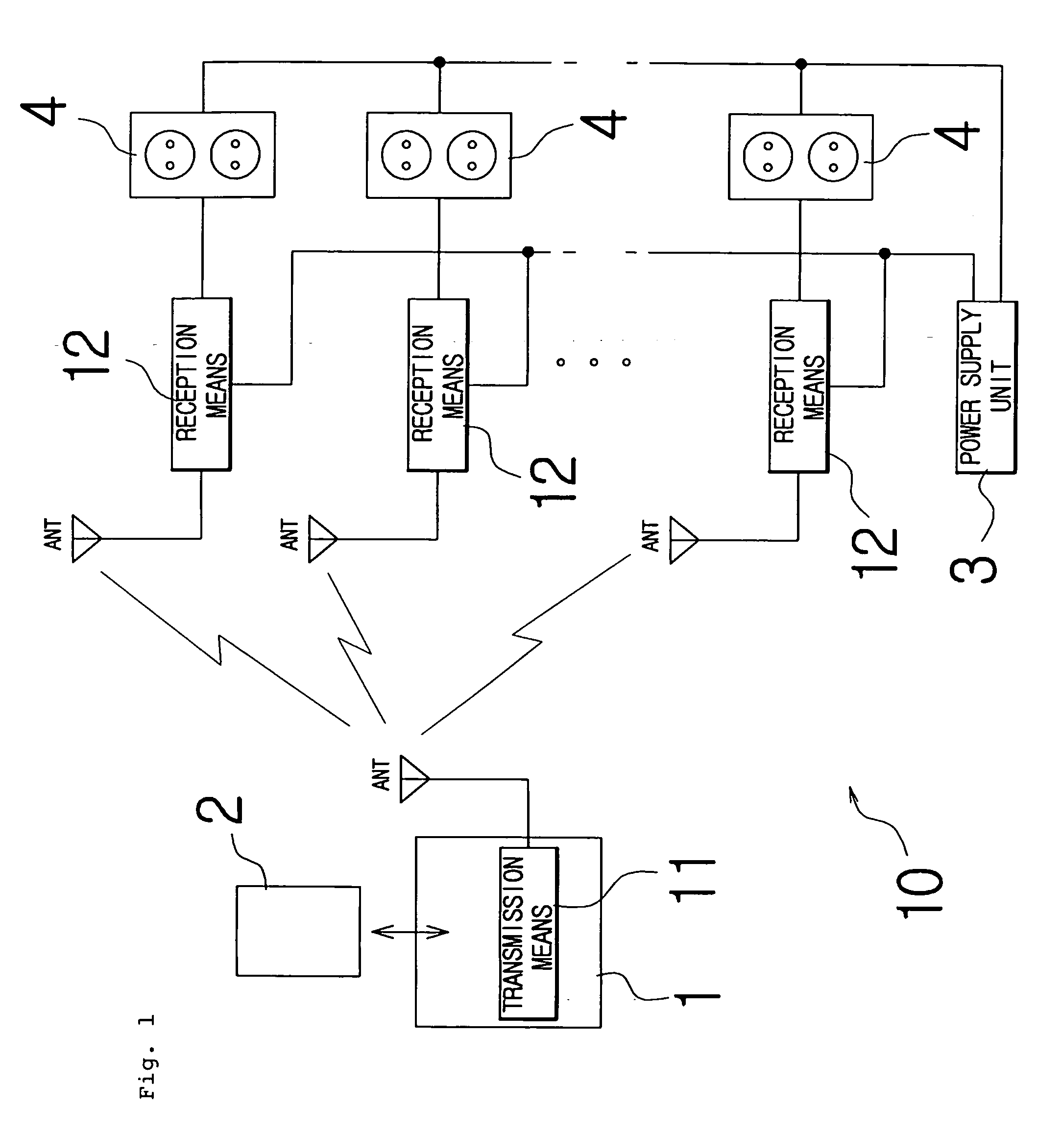
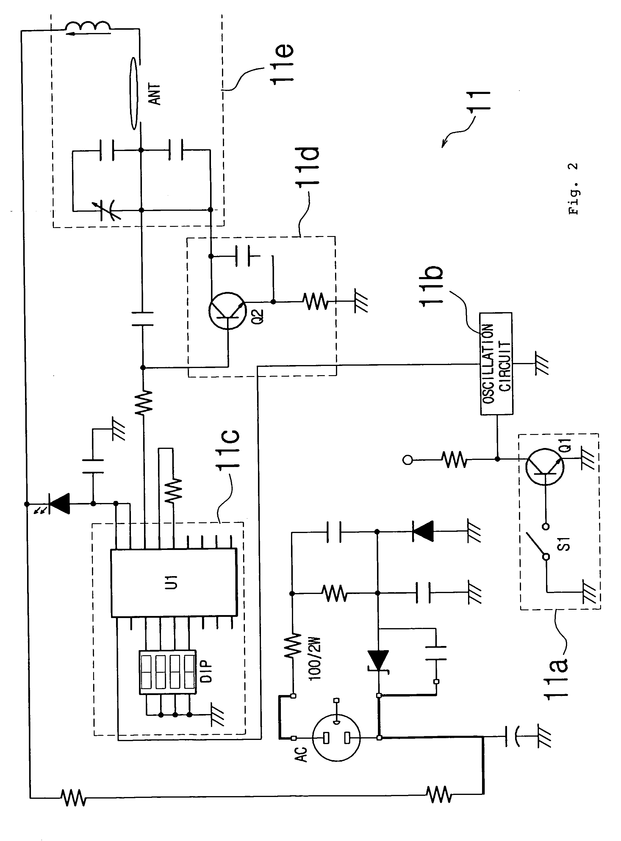
[0017]Before the present invention is described, the attached drawings, provided in order to understand the technique of the present invention, will be described. FIG. 1 is a block diagram and FIGS. 2 and 3 are circuit diagrams, which show configuration according to an embodiment of the present invention. Reference number 10 indicates a power on and off system according to the present invention.

[0018]The present invention will be described with reference to the attached drawings below.

[0019]First, as shown in FIG. 1, the present invention provides a power on and off system 10, which selectively supplies power of a power supply unit 3 and cuts off the supply of power between the power supply unit 3 and at least one electric outlet 4 depending on the insertion of a door card key 2 into a door card key receptacle...


PUM


Abstract

Disclosed herein is a system for turning on and off power using a door card key. Transmission means includes a switch unit turned on and off depending on the insertion of the door card key, a switch monitoring unit configured to generate a clock signal, a microcomputer unit configured to generate an RF signal, a transmission signal amplification unit configured to amplify the RF signal generated by the microcomputer unit, and a transmission unit configured to transmit the amplified RF signal. Reception means includes a reception unit configured to receive the RF signal from the transmission means, a reception signal amplification unit configured to amplify the RF signal from the reception unit, a drive signal generation unit configured to convert the RF signal into a drive signal and then output the drive signal, and a control switch unit turned on and off in response to the drive signal.

Description

BACKGROUND OF THE INVENTION[0001]1. Field of the Invention[0002]The present invention relates to a system for turning on and off power using a door card key.[0003]2. Description of the Related Art[0004]Generally, when a door card key is inserted into a door card key receptacle inside the door, a system for turning on and off power using a door card key performs a switching operation and supplies power to one or more electric devices installed in a predetermined region.[0005]In a prior art system for turning on and off power using a door card key, various electric devices, such as a refrigerator, a television, a microwave oven, an audio player, and an electric light, are connected to electric outlets. The electric outlets are connected to one end of a switch provided in the door card key receptacle, and a power supply device is connected to the other end of the switch.[0006]In the prior art system for turning on and off power using a door card key, when a door card key is inserted in...

Claims


Application Information

Patent Timeline
IPC IPC(8): G06K19/00
CPCG07C9/00658H04M11/007
Inventor PARK, SE YOUNG
Owner PARK SE YOUNG
Why Eureka
Try Eureka