
Controlling device and system

a control device and control device technology, applied in the direction of electric controllers, program control, instruments, etc., can solve the problems of inability to control the direction of infrared rays the limitation of the infrared ray direction of the remote controller, and the inability to control the direction of infrared rays

Inactive Publication Date: 2009-12-31
DELTA ELECTRONICS INC
View PDF4 Cites 144 Cited by
  • Summary
  • Abstract
  • Description
  • Claims
  • Application Information

AI Technical Summary

Benefits of technology

[0007]To achieve the above, the present invention discloses a controlling device including a controller, a Human-Machine Interface (HMI) device, a power supply and a power line network signal transmit/receive module. The HMI device is connected to the controller. The power supply provides an electric

Problems solved by technology

However, the remote controller has the limitation of direction of the infrared ray, and the signal transmission is easily blocked by walls.
Thus, the application of the IR remote controller is usually restricted to a single room.
In addition, the IR remote controller is usually a one-way controller so that the remote controller can not display the operation status of the electronic device.
This may cause inconvenience of the users.

Method used


Image

  • Controlling device and system
  • Controlling device and system
  • Controlling device and system

Examples


Embodiment Construction

[0014]The present invention will be apparent from the following detailed description, which proceeds with reference to the accompanying drawings, wherein the same references relate to the same elements.

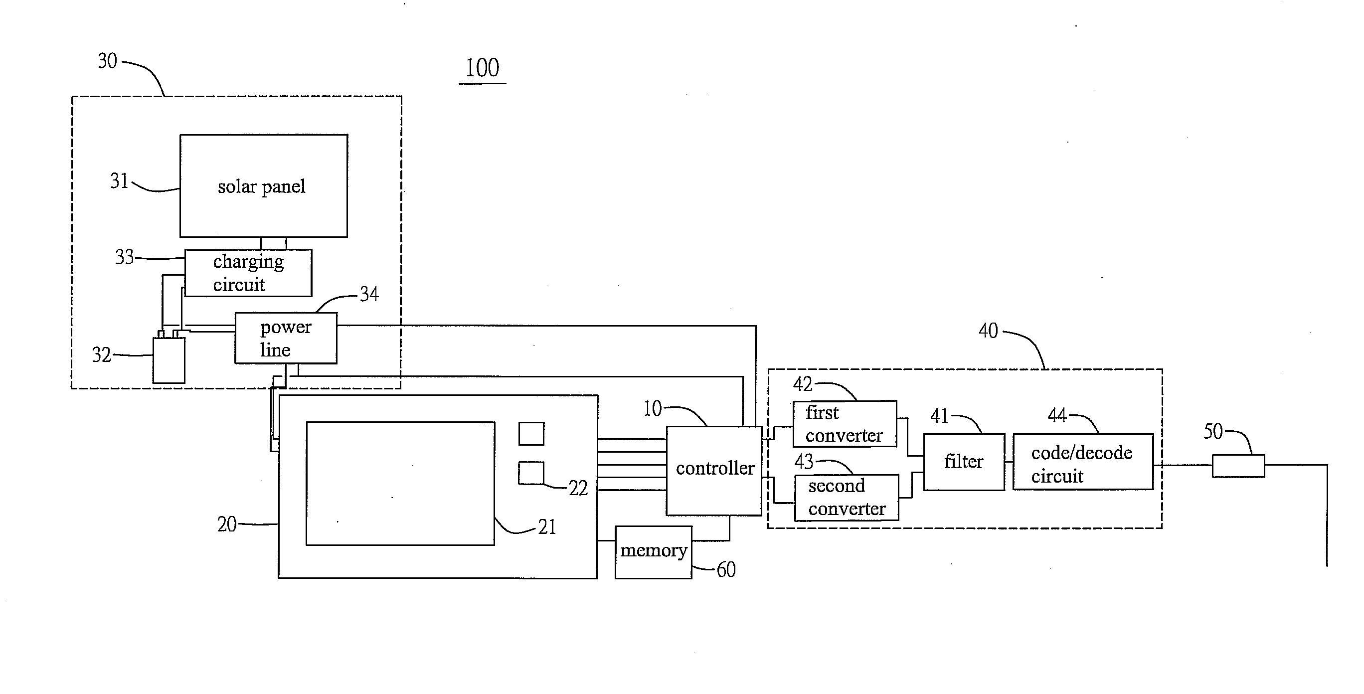
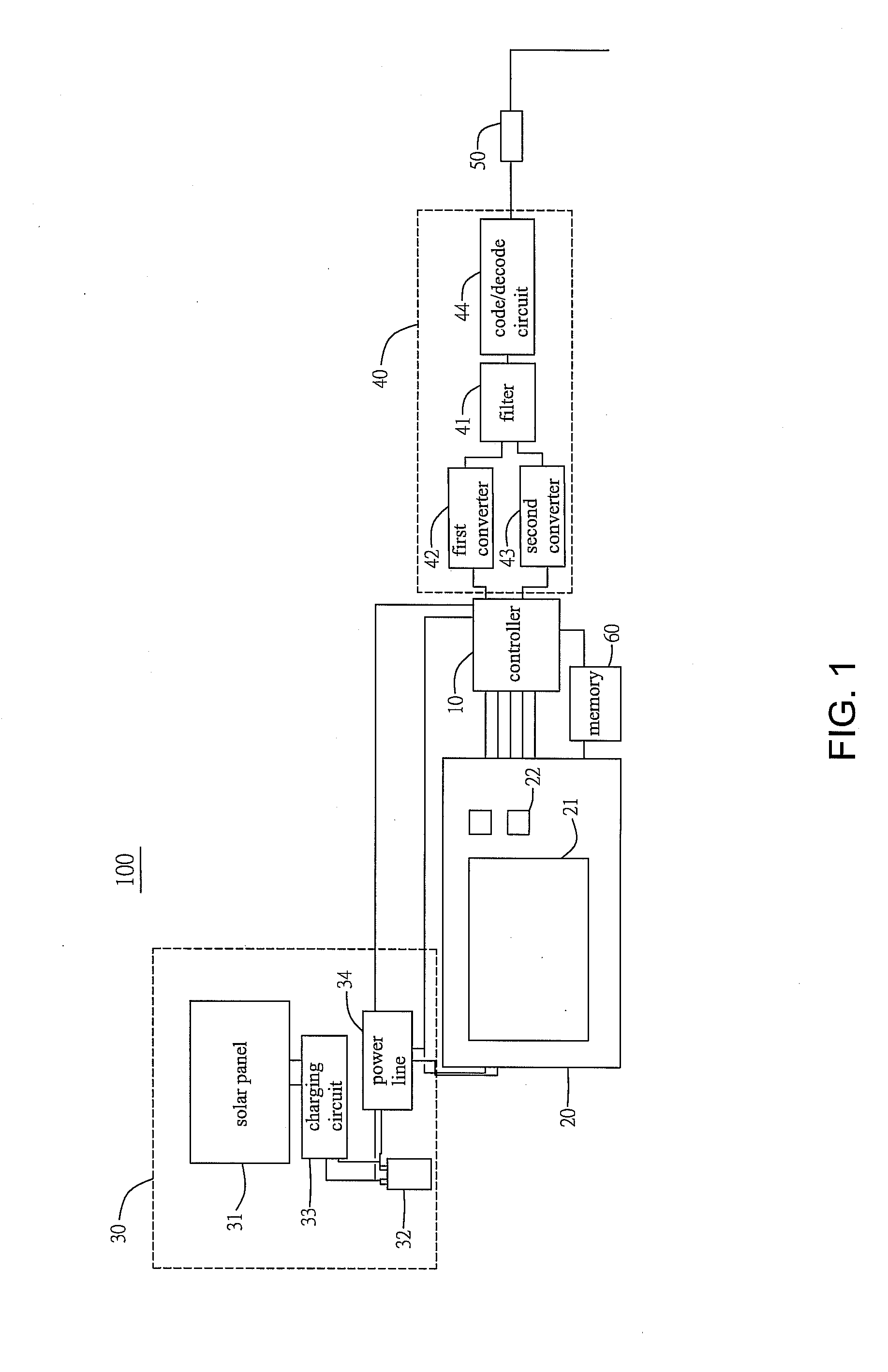
[0015]FIG. 1 is a schematic illustration showing a controlling device 100 according to an embodiment of the present invention. The controlling device 100 includes a controller 10, a Human-Machine Interface (HMI) device 20, a power supply 30 and a power line network signal transmit / receive module 40. The HMI device 20 is connected to the controller 10. The power supply 30 provides an electric power to the controller 10 and the HMI device 20, respectively. The power line network signal transmit / receive module 40 is connected to the controller 10.

[0016]The power supply 30 can include a dry battery or a solar charging module. FIG. 1 shows an aspect of the power supply 30, which is a solar charging module. In the embodiment, the power supply 30 includes a solar panel 31, a battery 32, a ch...


PUM


Abstract

A controlling device and a controlling system. The controlling device transmits controlling signals to an electronic device and receives operation statuses thereof through a power line. The controlling device includes a Human-Machine Interface (HMI) device for displaying the operation statuses of the electronic device. The controlling device includes a controller, an HMI device connected to the controller, a power supply for providing an electric power to the controller and the HMI device, and a power line network signal transmit / receive module connected to the controller.

Description

CROSS REFERENCE TO RELATED APPLICATIONS[0001]This Non-provisional application claims priority under 35 U.S.C. §119(a) on Patent Application No(s). 097124508 filed in Taiwan, Republic of China on Jun. 30, 2008, the entire contents of which are hereby incorporated by reference.BACKGROUND OF THE INVENTION[0002]1. Field of Invention[0003]The present invention relates to a controlling device and a system. More particularly, the present invention relates to a controlling device and a system, which can control the electronic device and receive the operation statuses of the electronic device through a power line.[0004]2. Related Art[0005]The electronic devices, such as the household appliances, are usually controlled by remote controllers. The conventional remote controller utilizes the infrared ray (IR) to transmit signals. However, the remote controller has the limitation of direction of the infrared ray, and the signal transmission is easily blocked by walls. Thus, the application of the...

Claims


Application Information

Patent Timeline
IPC IPC(8): G06F17/00G05B11/01
CPCG05B2219/2642G05B15/02
Inventor LEE, CHI-CHING
Owner DELTA ELECTRONICS INC
Learn More