Lens master devices, lens structures, imaging devices, and methods and apparatuses of making the same

a technology of lens master device and lens structure, applied in the field of lens master device, lens structure, imaging device, and methods and apparatuses of making the same, can solve problems such as limited capabilities of techniques

Active Publication Date: 2009-12-31
MICRON TECH INC
View PDF13 Cites 201 Cited by
  • Summary
  • Abstract
  • Description
  • Claims
  • Application Information

AI Technical Summary

Problems solved by technology

When they are employed to form objective lenses used in imaging devices, these techniques may be limited in their ability to create desired shapes

Method used


Image

  • Lens master devices, lens structures, imaging devices, and methods and apparatuses of making the same
  • Lens master devices, lens structures, imaging devices, and methods and apparatuses of making the same
  • Lens master devices, lens structures, imaging devices, and methods and apparatuses of making the same

Examples


Embodiment Construction

[0014]In the following detailed description, reference is made to the accompanying drawings, which form a part hereof and show by way of illustration specific embodiments and examples that may be practiced. These embodiments and examples are described in sufficient detail to enable those skilled in the art to practice them. It is to be understood that other embodiments and examples may be utilized, and that structural, logical, and electrical changes and variations may be made. Moreover, the progression of processing steps is described as an example; the sequence of steps is not limited to that set forth herein and may be changed, with the exception of steps necessarily occurring in a certain order.

[0015]The term “substrate” used herein may be any supporting structure including, but not limited to, a semiconductor substrate having a surface on which devices can be fabricated. A semiconductor substrate should be understood to include silicon, silicon-on-insulator (SOI), silicon-on-sa...


PUM

PropertyMeasurementUnit
Heightaaaaaaaaaa

Abstract

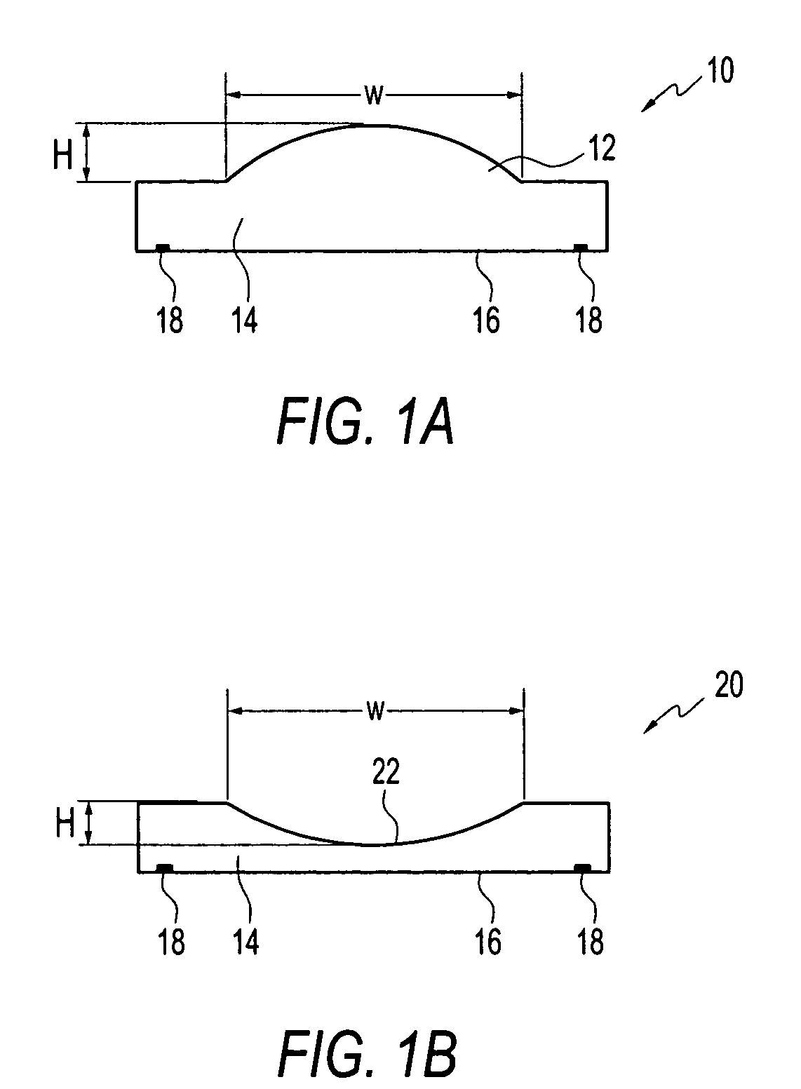
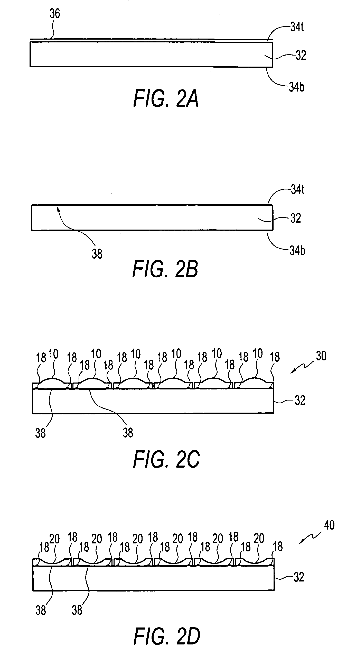
A method and apparatus providing a lens master device and use of the same to form a lens template and/or a lens structure. The method includes obtaining a plurality of individual lens masters, each of which has a shaped portion defining at least a portion of a lens structure to be formed. The lens masters are affixed onto a supporting structure to form a lens master device.

Description

FIELD OF THE INVENTION[0001]Embodiments of the invention relate generally to lens master devices, lens structures, imaging devices, and methods and apparatuses of making the same.BACKGROUND OF THE INVENTION[0002]Lenses have been used in various applications including, without limitation, flat-panel visual displays, solar panels, digital cameras, camera telephones, video telephones, computer input devices, scanners, machine vision systems, vehicle navigation systems, surveillance systems, auto focus systems, star trackers, motion detector systems, and image stabilization systems among other imager and display applications.[0003]Lenses can operate in any of various ways. For example, in an imaging device, an objective lens is typically used in association with a pixel array to collect and focus incident light impinged on the objective lens onto the underlying associated pixel array. As a result, incident light can be more efficiently directed to and absorbed by the various photosensit...

Claims


Application Information

Patent Timeline
IPC IPC(8): G02B9/02
CPCB29D11/00278G02B3/0025G02B3/005G02B3/0056G02B3/0031
Inventor HEMBREE, DAVID R.OLIVER, STEVE
Owner MICRON TECH INC
Why Eureka
Try Eureka