Method of identifying speakers in a home theater system

a home theater system and speaker technology, applied in stereophonic systems, stereophonic arrangments, electrical appliances, etc., can solve the problems of not meeting the industry standard for mapping speaker positions to i2s bus channels, placement of subwoofers, and timing of audio signals for driving subwoofers, etc., to achieve satisfactory operation of home theater systems

Active Publication Date: 2009-12-31
WISA TECH INC
View PDF8 Cites 48 Cited by
  • Summary
  • Abstract
  • Description
  • Claims
  • Application Information

AI Technical Summary

Benefits of technology

[0012]In accordance with a sixth aspect of the disclosed subject matter there is provided a method of optimizing a speaker system that includes a center speaker, multiple left speakers and multiple right speakers for a listener at a selectively variable location, wherein each speaker includes an ultrasonic electro-acoustic transducer, the method comprising positioning a portable location measurement device including an ultrasonic electro-acoustic transducer at a selected location and using the portable location measurement device to initiate a measurement procedure by which the transducers of at least two speakers emit ultrasonic ping signals, the transducer of the location measurement device detects the ultrasonic ping signals, and lapse of time between emission of the ping signal and detection of the ping signal by the transducer of the location measurement device is measured, allowing calculation of the position of the measurement location device relative to the speakers, whereby relative signal delays to the speakers may be adjusted to account for the position of the location measurement device.

Problems solved by technology

However, there is no industry standard for mapping speaker position to I2S bus channel.
The subwoofer conveys low frequency information and the placement of the subwoofer and the timing of the audio signal for driving the subwoofer are not critical to satisfactory operation of the home theater system.

Method used


Image

  • Method of identifying speakers in a home theater system
  • Method of identifying speakers in a home theater system
  • Method of identifying speakers in a home theater system

Examples


Embodiment Construction

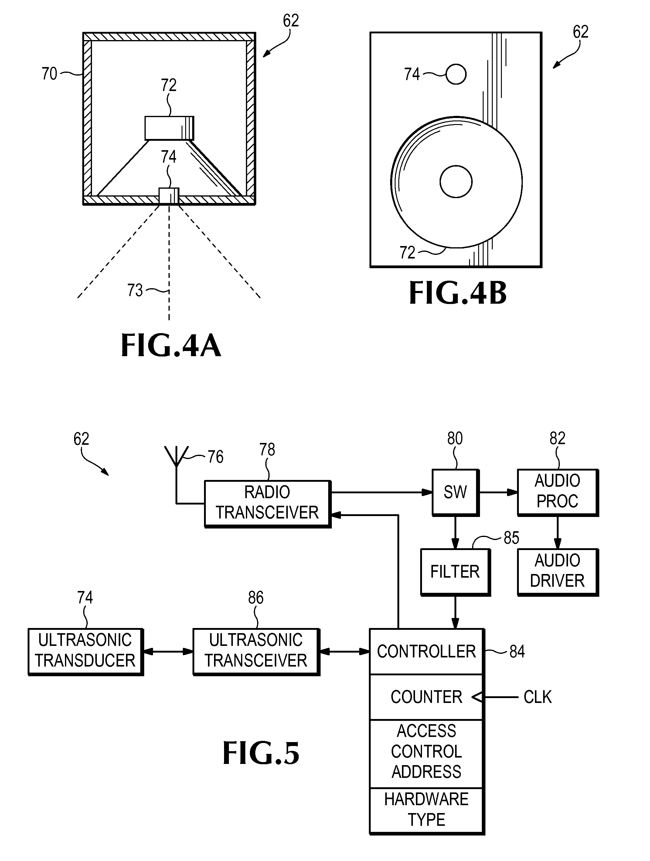
[0021]As used in this detailed description and in the appended claims, the term “audio” as applied to a signal means a signal having a frequency within the accepted standard range of audible frequencies, i.e. from 20 Hz to 20,000 Hz, whereas “ultrasonic” as applied to a signal means a signal having a frequency higher than 20 kHz. As applied to an electro-acoustic transducer, the term “ultrasonic” as used herein means that the transducer is able to emit and receive ultrasonic acoustic signals.

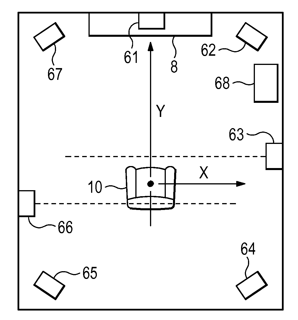
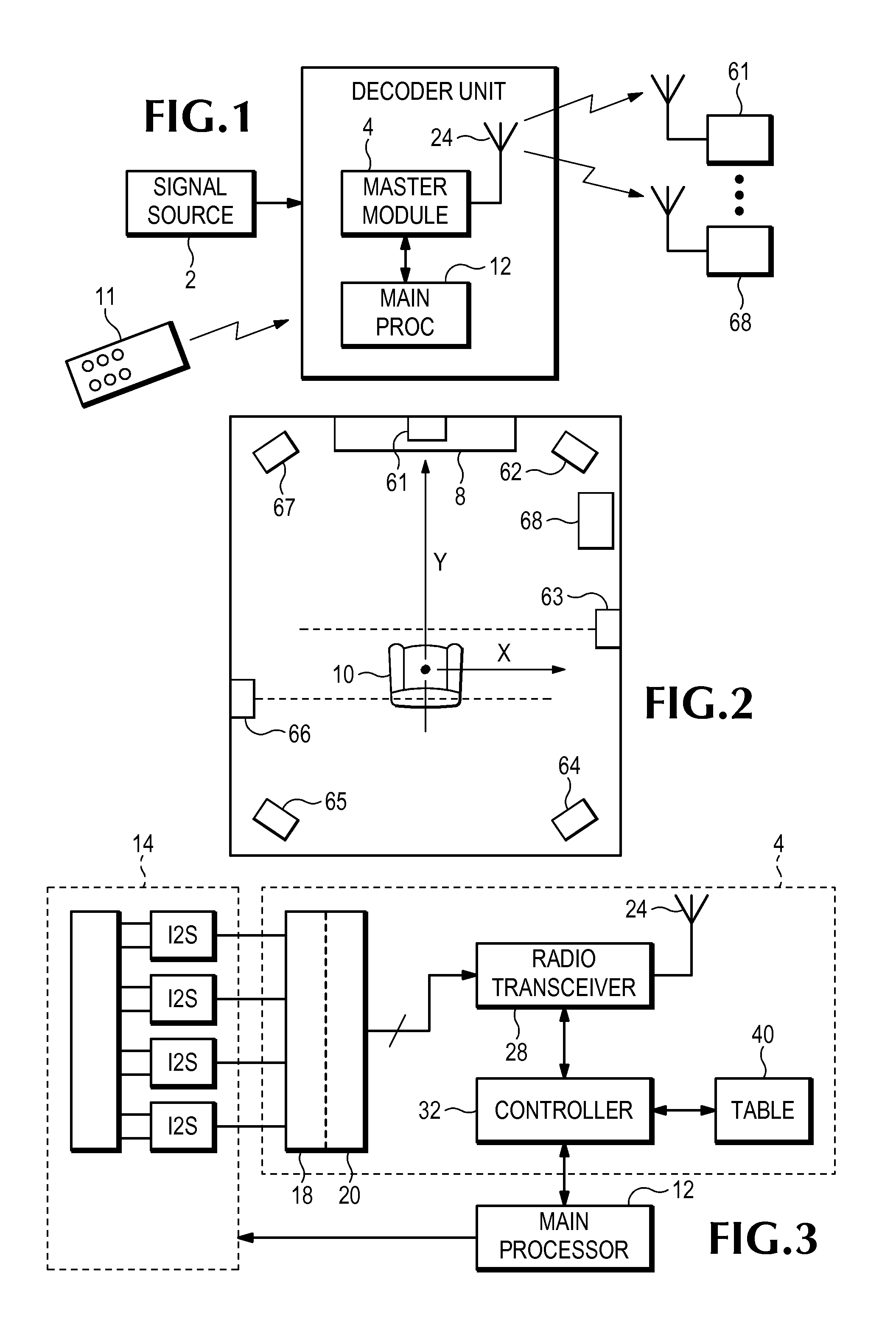
[0022]The 7.1 channel home theater system shown in FIG. 1 comprises a signal source 2, which may, for example, be a satellite receiver, a cable TV decoder or a DVD player, eight speakers 61-68 (a center speaker 61, six surround speakers 62-67 and a subwoofer 68) and a display unit 8. The home theater system also includes a home theater decoder 14 (FIG. 3), which receives audio data from the signal source and generates four I2S serial bus signals, as described above. The home theater decoder may ...


PUM


Abstract

With an array of speakers including a center speaker provided with left and right ultrasonic electro-acoustic transducers and left and right speakers provided with respective ultrasonic electro-acoustic transducers, it is possible to identify the left and right speakers. One approach includes energizing the left transducer of the center speaker to emit an acoustic ping signal, utilizing the transducers of the left and right speakers to detect the ping signal, measuring lapse of time between emission of the ping signal by said the left transducer and detection of the ping signal by the transducers of the left and right speakers. Then, the right transducer of the center speaker is energized to emit an acoustic ping signal, the transducers of the left and right speakers are utilized to detect the ping signal, and lapse of time between emission of the ping signal by the right transducer and detection of the ping signal by the transducers of the left and right speakers is measured.

Description

CROSS-REFERENCE TO RELATED APPLICATION[0001]This application claims benefit of U.S. Provisional Applications No. 61 / 074,899, 61 / 074,906, 61 / 074,910 and 61 / 074,914, all filed Jun. 23, 2008, the entire disclosure of each which is hereby incorporated herein by reference for all purposes.BACKGROUND OF THE INVENTION[0002]The subject matter of this application relates to a method of identifying speakers in a home theater system.[0003]A typical home theater system comprises a display unit, a DVD player or other signal source, an audio video control receiver, and multiple speakers. A so-called 7.1 channel system uses eight speakers, namely a center speaker, a subwoofer and six surround speakers (right and left front, right and left fill and right and left rear). The home theater system includes a home theater decoder which creates eight digital audio signals, which are assigned to the eight speakers respectively, from data that the DVD player reads from the disk. We will assume for the purp...

Claims


Application Information

Patent Timeline
Patent Type & Authority Applications(United States)
IPC IPC(8): H04R5/02
CPCH04S7/00H04R2420/07H04S7/301H04S7/308
Inventor HUDSON, MICHAEL D.MCARTHUR, KELLY M.LIEBELT, RICHARD S.KLINKER, JR., JOHN W.
Owner WISA TECH INC
Why Eureka
Try Eureka