

Rotor blade monitoring
- Summary
- Abstract
- Description
- Claims
- Application Information
AI Technical Summary
Benefits of technology
Problems solved by technology
Method used
Image

Examples
Embodiment Construction
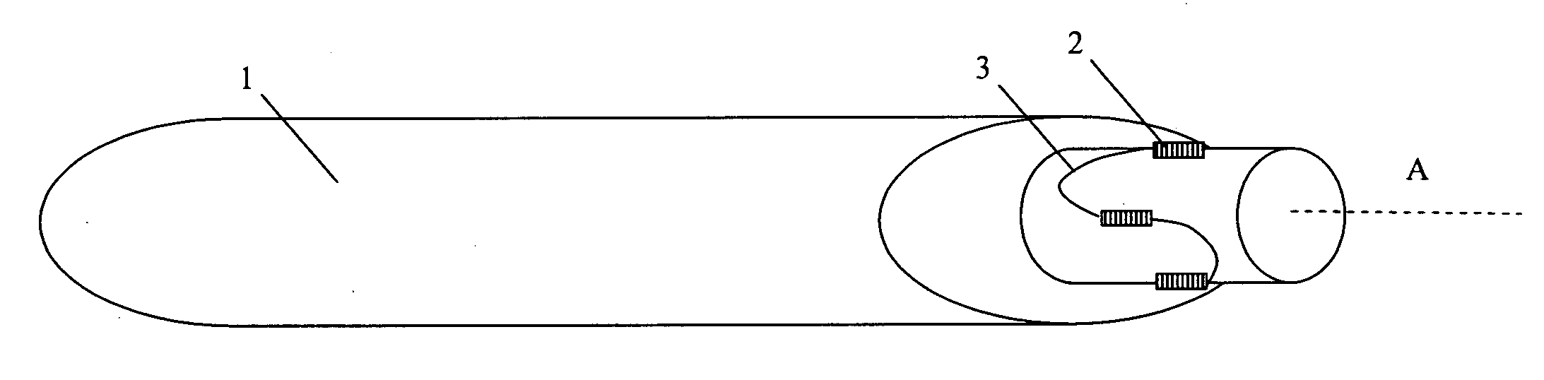
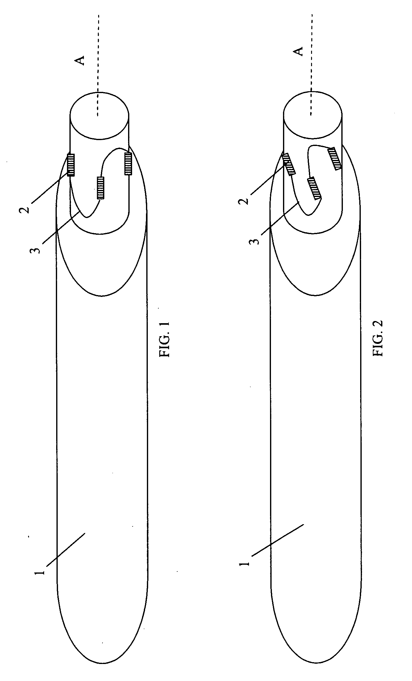
[0033]FIG. 1 is a schematic view of a helicopter rotor blade 1 provided with optical fibre strain sensors 2 according to one embodiment of the invention. The strain sensors 2 are provided as fibre Bragg grating (FBG) sensors in an optical fibre 3 in known manner. Suitable optical fibre strain sensor systems are described for example in our European Patent 02258640.8. The strain sensors 2 are mounted to the periphery of the base of the blade 1 and are arranged to measure strain in directions parallel to the longitudinal axis A of the blade 1. In this embodiment, four strain sensors 2 are provided and are equally distributed about the axis. By resolving the strain measurements from pairs of sensors 2, the mechanical load on the rotor blade 1 in the longitudinal axial direction, and about two orthogonal axes can be determined. The optical fibre strain sensors 2 are sufficiently responsive that the measured load signals represent the vibration of the rotor blade 1. Because the strain se...
PUM
 Abstract
Description
Claims
Application Information