Fluidized bed reactor systems and methods for reducing the deposition of silicon on reactor walls

a reactor and flue-bed technology, applied in the direction of silicon compounds, lighting and heating apparatus, furnaces, etc., can solve the problems of reducing the reactor productivity, reducing the reactor performance, and reducing the deposition of silicon on the reactor walls, so as to reduce the amount of silicon

a reactor and flue-bed technology, applied in the direction of silicon compounds, lighting and heating apparatus, furnaces, etc., can solve the problems of reducing the reactor productivity, reducing the reactor performance, and reducing the deposition of silicon on the reactor walls, so as to reduce the amount of silicon

US20090324479A1Active Publication Date: 2009-12-31CORNER STAR LTD

Image

  • Fluidized bed reactor systems and methods for reducing the deposition of silicon on reactor walls
  • Fluidized bed reactor systems and methods for reducing the deposition of silicon on reactor walls
  • Fluidized bed reactor systems and methods for reducing the deposition of silicon on reactor walls

Examples


example 1

Computer Simulated Comparison of Conventional Deposition and Deposition According to Embodiments of the Present Invention

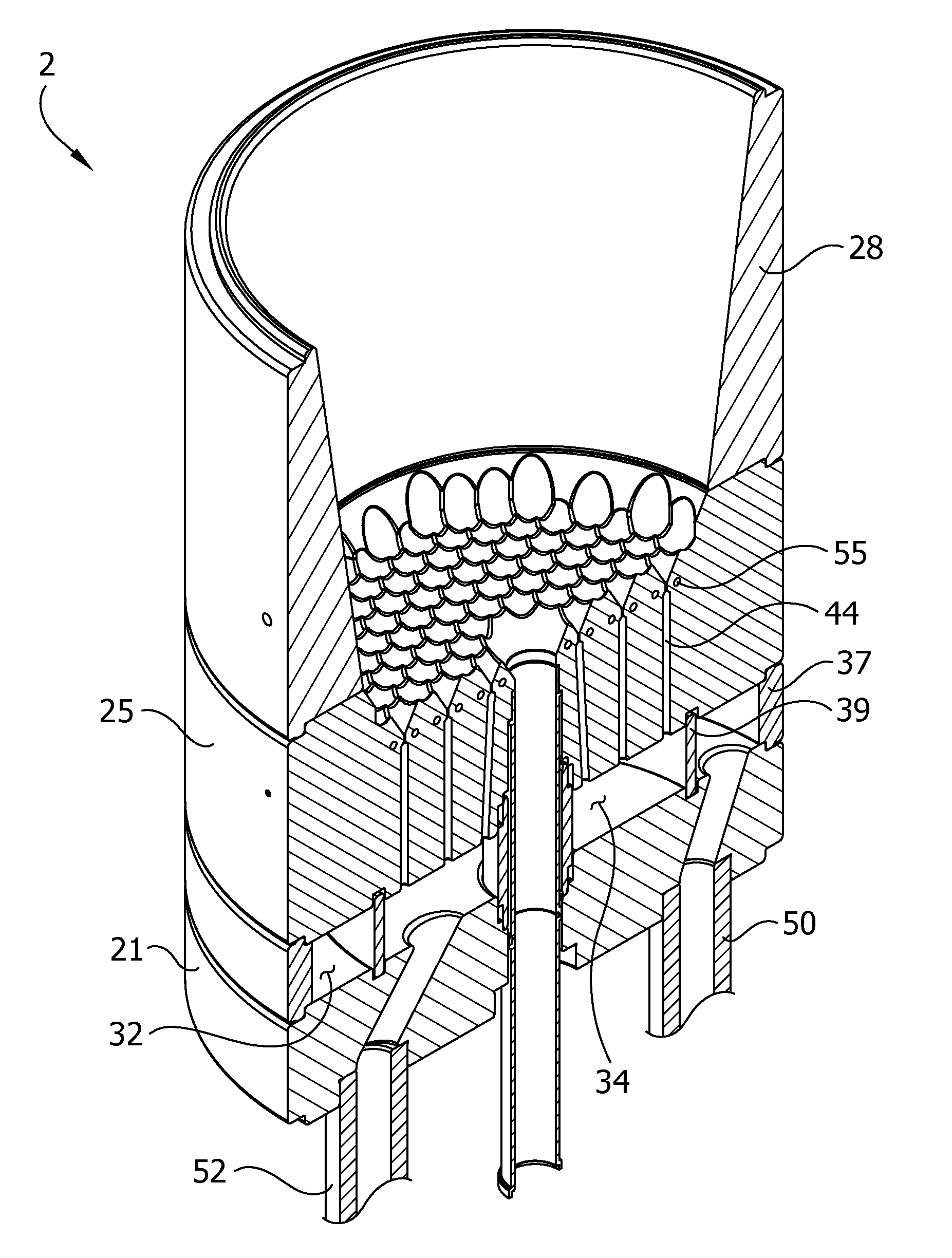
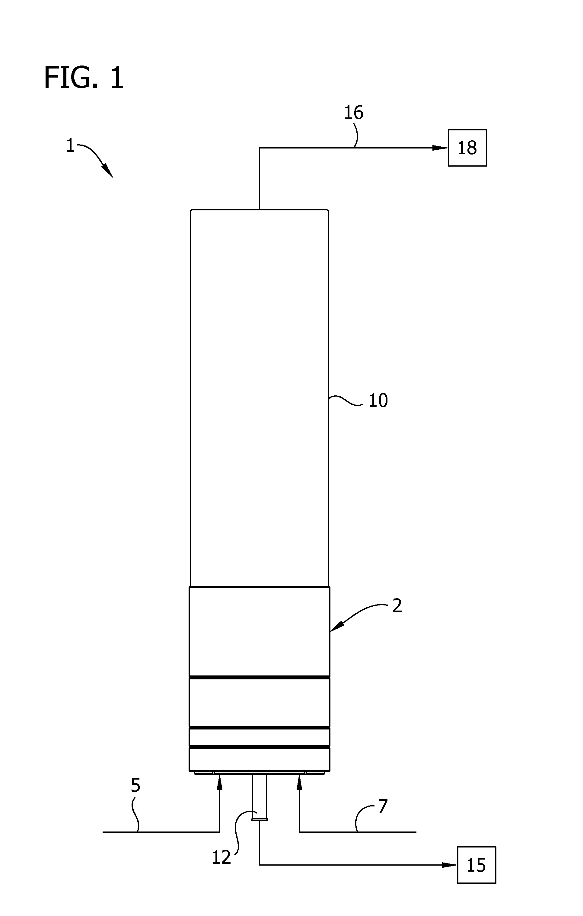
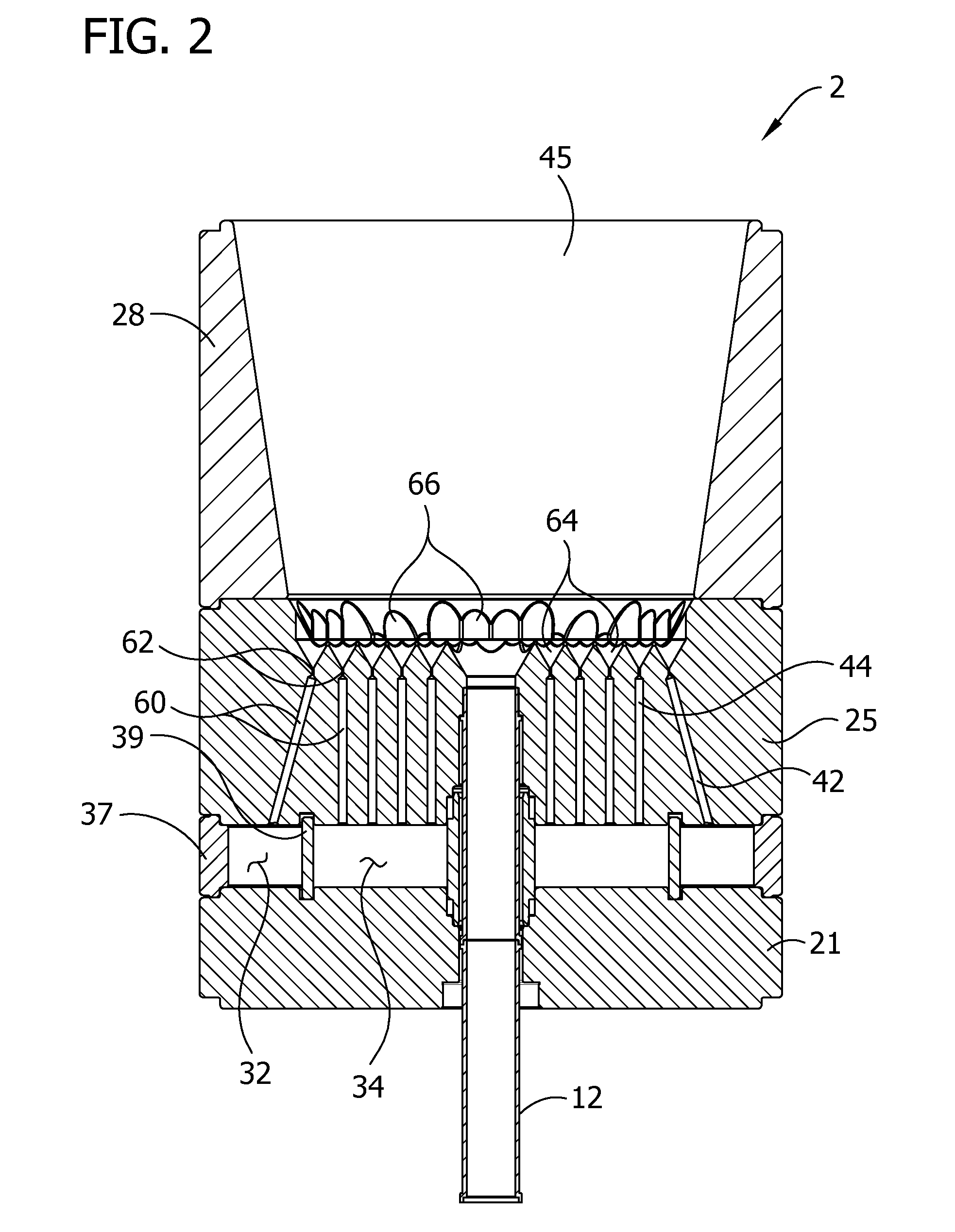
[0054]The deposition rates of silicon on the wall of a reaction chamber (including deposition on the inner surface of the taper liner of the liner chamber) over the length of the reactor under two computer simulations are shown in FIG. 8. Position “0” represents the bottom of the taper liner 28 (FIG. 6). The data points illustrated by triangles (i.e., the data line with the higher peak) depict the deposition rates over the length of a fluidized bed reactor operated by conventional methods and the data points illustrated by circles (i.e., the data line with the lower peak) depict the deposition rates over the length of a fluidized bed reactor shown in FIGS. 1-6 and described above. Both simulations used hydrogen as a carrier gas and silane was used as the thermally decomposable compound. In the reactor operated by conventional deposition methods, hydrogen and silan...


PUM


Abstract

Gas distribution units of fluidized bed reactors are configured to direct thermally decomposable compounds to the center portion of the reactor and away from the reactor wall to prevent deposition of material on the reactor wall and process for producing polycrystalline silicon product in a reactor that reduce the amount of silicon which deposits on the reactor wall.

Description

CROSS-REFERENCE TO RELATED APPLICATION[0001]This application claims the benefit of U.S. Provisional Application No. 61 / 076,886, filed Jun. 30, 2008, the entire contents of which are incorporated herein by reference for all relevant and consistent purposes.BACKGROUND OF THE INVENTION[0002]This invention relates to fluidized bed reactor systems and to the production of polycrystalline silicon from a thermally decomposable silicon compound such as, for example, silane.[0003]Fluidized bed reactors are used to carry out multiphase reactions. In typical fluidized bed reactor systems a fluid is passed through a bed of granular material such as a catalyst or growing product particles. The flow of fluid causes the bed of granular material to become fluidized in the reactor.[0004]In many fluidized bed reactor systems and especially in systems where material from the fluid phase chemically decomposes to form solid material, solids may deposit onto the walls of the reactor. The wall deposits of...

Claims


Application Information

Patent Timeline
31 Dec 2009
Publication
US20090324479A1
IPC
C01B33/02; F27B15/00; F27B15/09
CPC
B01J8/1818; C01B33/027; B01J2219/00252; B01J8/44
Inventors
KULKARNI, MILIND S.; GUPTA, PUNEET