Proton exchange membrane fuel cell

Inactive Publication Date: 2009-12-31
HON HAI PRECISION IND CO LTD
View PDF2 Cites 3 Cited by
  • Summary
  • Abstract
  • Description
  • Claims
  • Application Information

AI Technical Summary

Problems solved by technology

However, many proton exchange membrane fuel cells have low efficiency in

Method used


Image

  • Proton exchange membrane fuel cell
  • Proton exchange membrane fuel cell
  • Proton exchange membrane fuel cell

Examples


Example

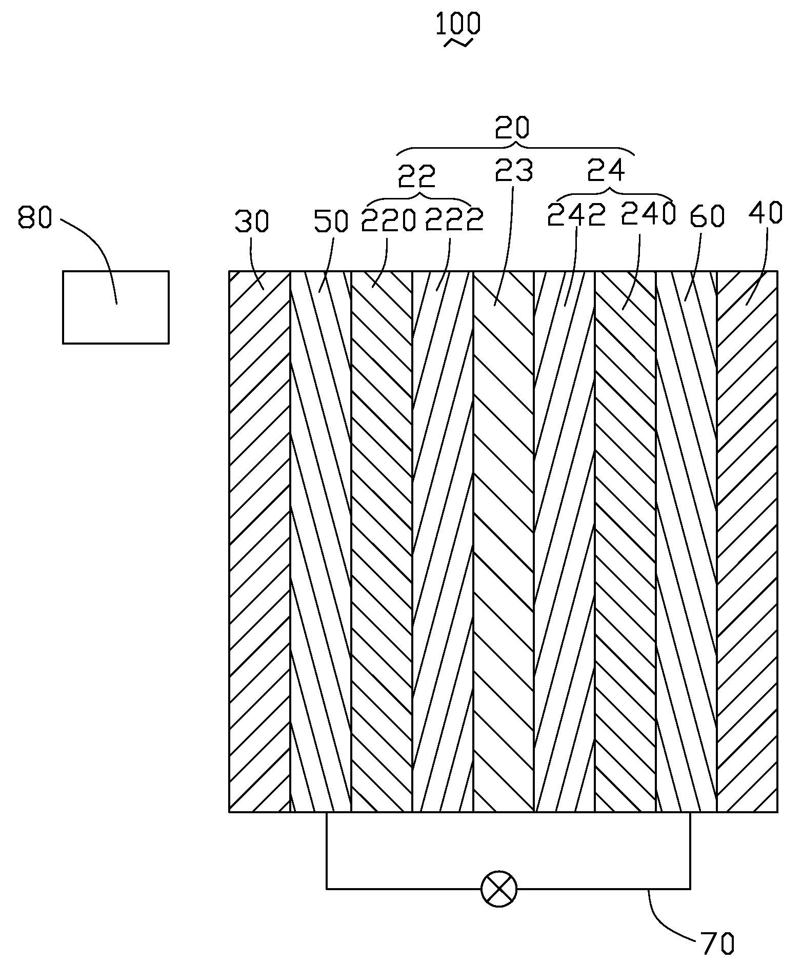
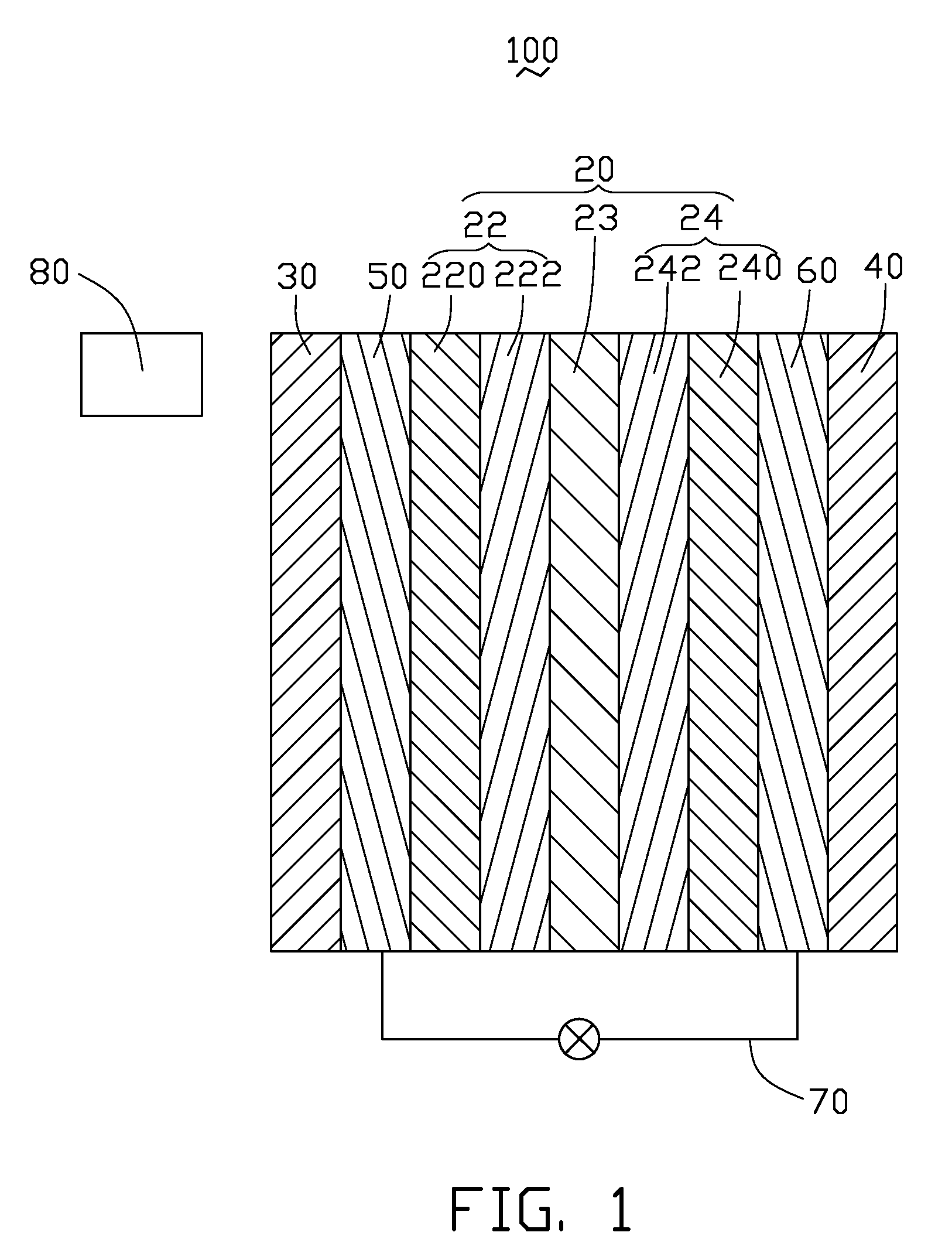
[0010]Referring to FIG. 1, a proton exchange membrane fuel cell 100, in accordance with an exemplary embodiment, includes a membrane electrode assembly 20, a first end plate 30, a second end plate 40, a first bipolar plate 50, and a second bipolar plate 60. The first and second bipolar plates 50, 60 are arranged at opposite sides of and in contact with the membrane electrode assembly 20. In alternative embodiments, the first and second bipolar plates 50, 60 can be adjacent to the membrane electrode assembly 20 but not necessarily in contact with the membrane electrode assembly 20. The first and second end plates 30, 40 are arranged at opposite sides of the membrane electrode assembly 20, in contact with the first and second bipolar plates 50, 60, respectively. In alternative embodiments, the first and second end plates 30, 40 can be adjacent to the first and second bipolar plates 50, 60 but not necessarily in contact with the first and second bipolar plates 50, 60.

[0011]The membrane...


PUM


Abstract

An exemplary proton exchange membrane fuel cell includes a light-pervious first end plate, a second end plate, a light-pervious first bipolar plate, a second bipolar plate, and a membrane electrode assembly. The light-pervious first bipolar plate is arranged adjacent to the first end plate and capable of transmitting light having a given wavelength therethrough. The second bipolar plate is capable of having oxidant fed therein. The membrane electrode assembly includes a proton exchange membrane, and an anode and a cathode arranged at opposite sides of the proton exchange membrane. The anode is capable of having fuel fed therein, and includes a first catalyst layer containing photo-catalyst and noble metal such that the light is capable of activating the first catalyst layer to dissociate the fuel thereon.

Description

BACKGROUND[0001]1. Technical Field[0002]The present invention generally relates to fuel cells, and particularly to a proton exchange membrane fuel cell having high electric conversion efficiency.[0003]2. Description of Related Art[0004]A proton exchange membrane fuel cell is an electrochemical apparatus converting chemical energy into usable electric energy. The energy conversion occurs as a result of combination of a fuel (such as hydrogen or methanol) with an oxidant (such as pure oxygen or air containing oxygen). The proton exchange membrane fuel cell generally includes a membrane electrode assembly, two bipolar plates arranged at opposite sides of the membrane electrode assembly, and two end plates arranged at opposite sides of the bipolar plates. The membrane electrode assembly is comprised of an anode, a cathode, and a proton exchange membrane. In operation, a fuel is fed through one of the bipolar plates to the anode to be split into positive hydrogen ions (protons) and negat...

Claims


Application Information

Patent Timeline
IPC IPC(8): H01M8/10
CPCH01M4/9016H01M8/0204Y02E60/50H01M16/003H01M14/005
Inventor HUNG, HSIN-CHIN
Owner HON HAI PRECISION IND CO LTD
Why Eureka
Try Eureka