

Photocatalytic structures, methods of making photocatalytic structures, and methods of photocatalysis
a technology of photocatalysis and structure, applied in the field of photocatalysis structure, method of making photocatalytic structure, and method of photocatalysis, can solve the problem that the photocatalytic efficiency of tiosub>2 can only reach a certain level by itself, and achieve the effect of enhancing the catalytic activity
- Summary
- Abstract
- Description
- Claims
- Application Information
AI Technical Summary
Benefits of technology
Problems solved by technology
Method used
Image

Examples
example 1
Introduction
[0110]TiO2 is an efficient photocatalyst at ultraviolet and near visible light wavelengths for use in hydrogen production (A. Fujishima, K. Honda, Nature 238, 37 (1972); M-S. Park, M. Kang, M, Materials Letters 62, 183 (2007); N. Strataki, V. Bekiari, D. Kondarides, P. Lianos, Applied Catalysis B: Environmental 77, 184 (2007); J. F. Houlihan, D. P. Madasci, Materials Research Bulletin 11, 1191 (1976); J.-L. Desplat, Journal of Applied Physics 47, 5102 (1976), which are herein incorporated by reference for the corresponding discussion), self-cleaning (M. Houmard, D. Riassetto, F. Roussel, A. Bourgeois, G. Berthome, J. C. Joud, M. Langlet, Applied Surface Science 254, 1405 (2007); Y. Daiko, H. Yajima, T. Kasuga, Journal of European Ceramic Society 28, 267 (2007); S. S. Madaeni, N. Ghaemi, Journal of Membrane Science 303, 221 (2007), which are herein incorporated by reference for the corresponding discussion), and decomposing volatile organic compounds (V. Augugliaro, S. Co...
example 2
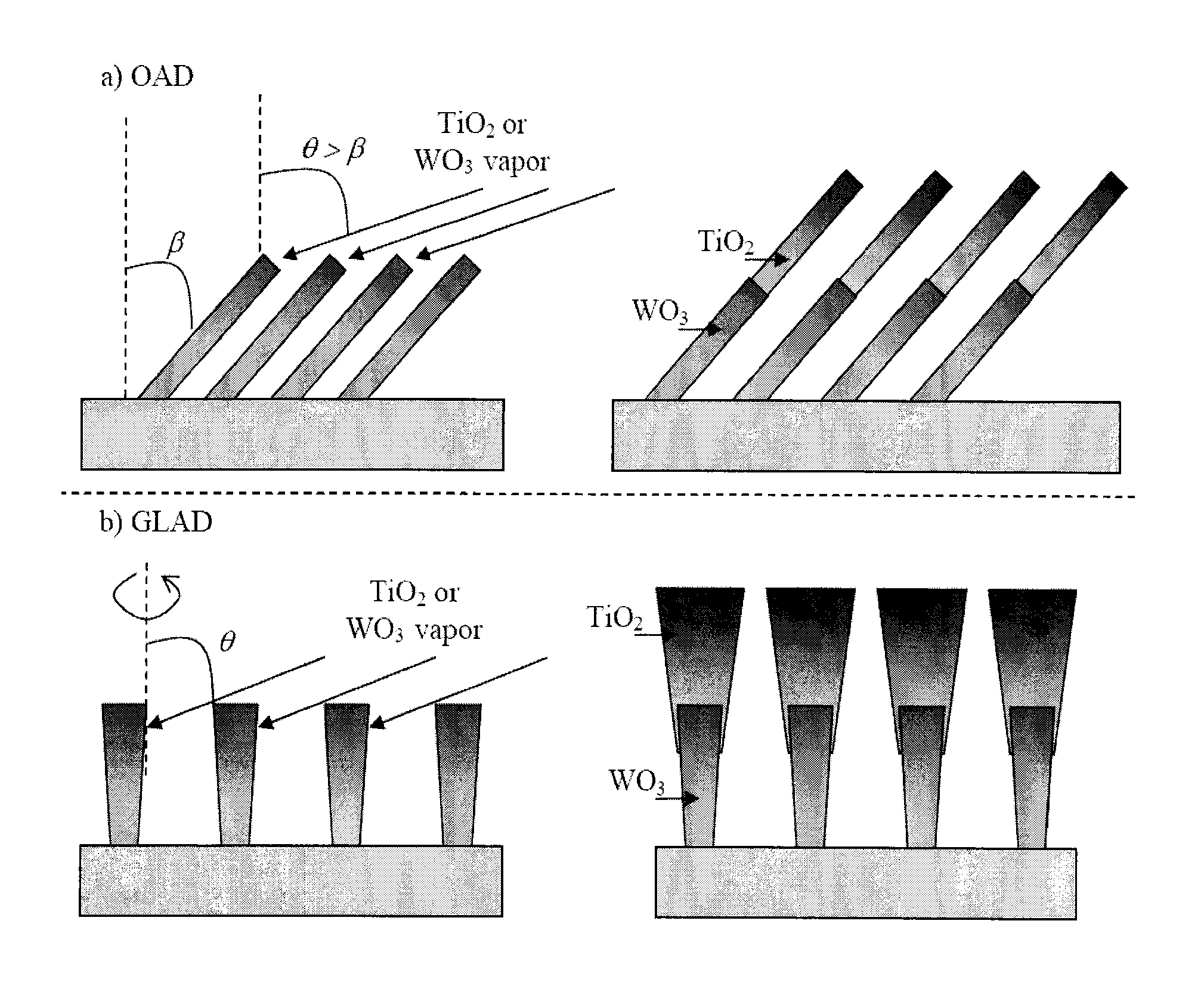
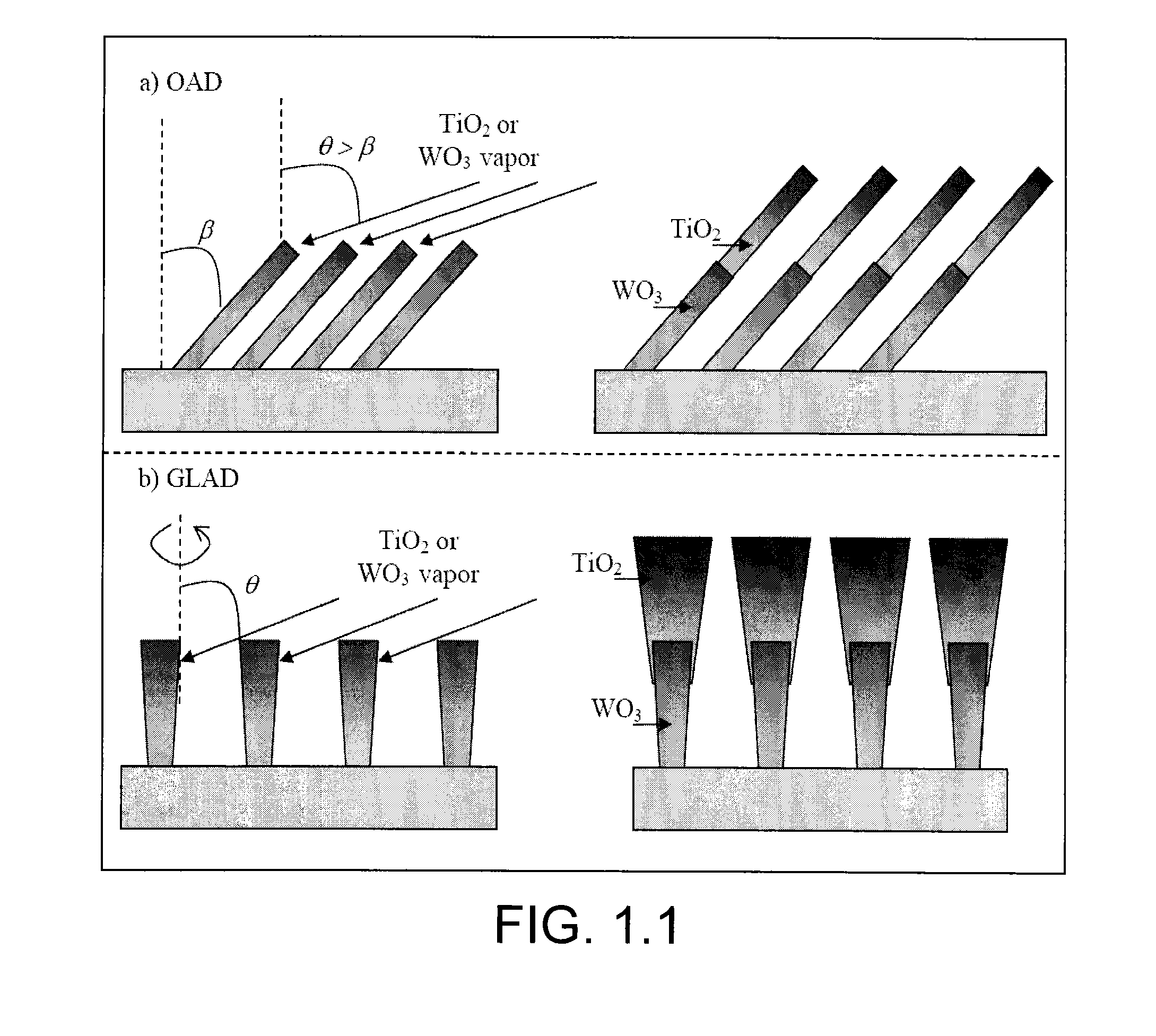
[0142]Using two consecutive regarding glancing angle depositions at different deposition angles and with different materials, a WO3-core TiO2-shell nanostructure has been fabricated and has photocatalytic enhancement up to 70 times over amorphous single layer TiO2 thin films, 13 times enhancement over crystalline (anatase) TiO2 thin films, and 3 times enhancement over c-TiO2 / a-WO3 two-layer thin films, with much less the load of TiO2. Without being bound by any particular theory, we believe that the mechanism for the photocatalytic enhancement is from the increased density of charge separated electron-hole pairs aided by the WO3 layer, the interfacial area between the two layers, and the large surface area from the porous nanostructure.
[0143]Two layered oxide nanostructures can significantly improve photocatalytic performance (A. Rampaul, I. Parkin, S. O'Neil, J. DeSouza, A. Mills, N. Elliot, Polyhedron 2003, 22, 35˜44; W. Gao, M. Li, R. Klie, E. I. Altman, J. Electron Spectrosc. Re...
example 3
[0155]This Example describes the photocatalytic activity of the core-shell embodiments in the visible light range. The following structures were fabricated and tested for photodegradation of methylene blue (MB). The samples were tested by putting them into a cuvette with ˜35 μM MB solution, and irradiated with different intensities of visible light. The range of visible light was from about 500 nm to 750 nm, with the strongest intensity lying between 600˜650 nm. We systematically changed the power intensity of the light hitting our photocatalytic samples, and measured the decay of MB over time for each sample. FIG. 3.1 is a plot of the decay of the MB solution as a function of time for several light intensities of visible light.
[0156]FIG. 3.1 illustrates that the MB solution degrades with visible light intensity ranging from 100 mW to 5 μW. The impact of this is that the solar spectrum of light from the sun is dominated by visible light, with an average light intensity of around 100...
PUM
| Property | Measurement | Unit |
|---|---|---|
| Temperature | aaaaa | aaaaa |
| Temperature | aaaaa | aaaaa |
| Length | aaaaa | aaaaa |
Abstract
Description
Claims
Application Information