Wear leveling in flash storage devices

Inactive Publication Date: 2009-12-31
HGST TECH SANTA ANA
View PDF17 Cites 63 Cited by
  • Summary
  • Abstract
  • Description
  • Claims
  • Application Information

AI Technical Summary

Benefits of technology

[0006]Various aspects of the subject disclosure solve the foregoing problem by providing improved wear leveling for flash storage

Problems solved by technology

Traditional EEPROM devices are only capable of erasing or writing one memory location at a time.
Due to flash memory's unique structure, however, each region of memory can only be rewritten a certain number of times before it can no longer

Method used


Image

  • Wear leveling in flash storage devices
  • Wear leveling in flash storage devices
  • Wear leveling in flash storage devices

Examples


Embodiment Construction

[0018]In the following detailed description, numerous specific details are set forth to provide a full understanding of the present invention. It will be apparent, however, to one ordinarily skilled in the art that the present invention may be practiced without some of these specific details. In other instances, well-known structures and techniques have not been shown in detail to avoid unnecessarily obscuring the present invention.

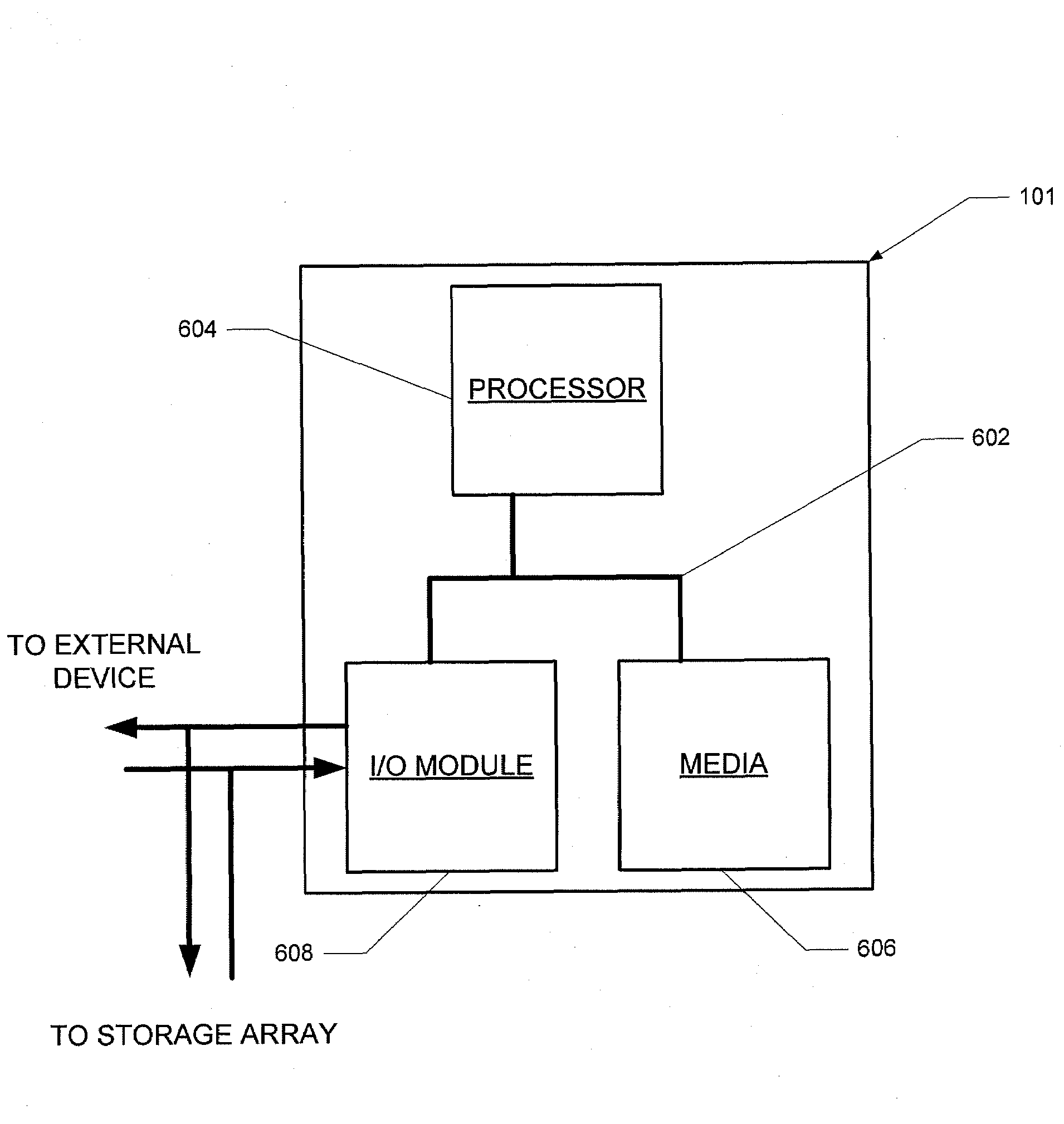
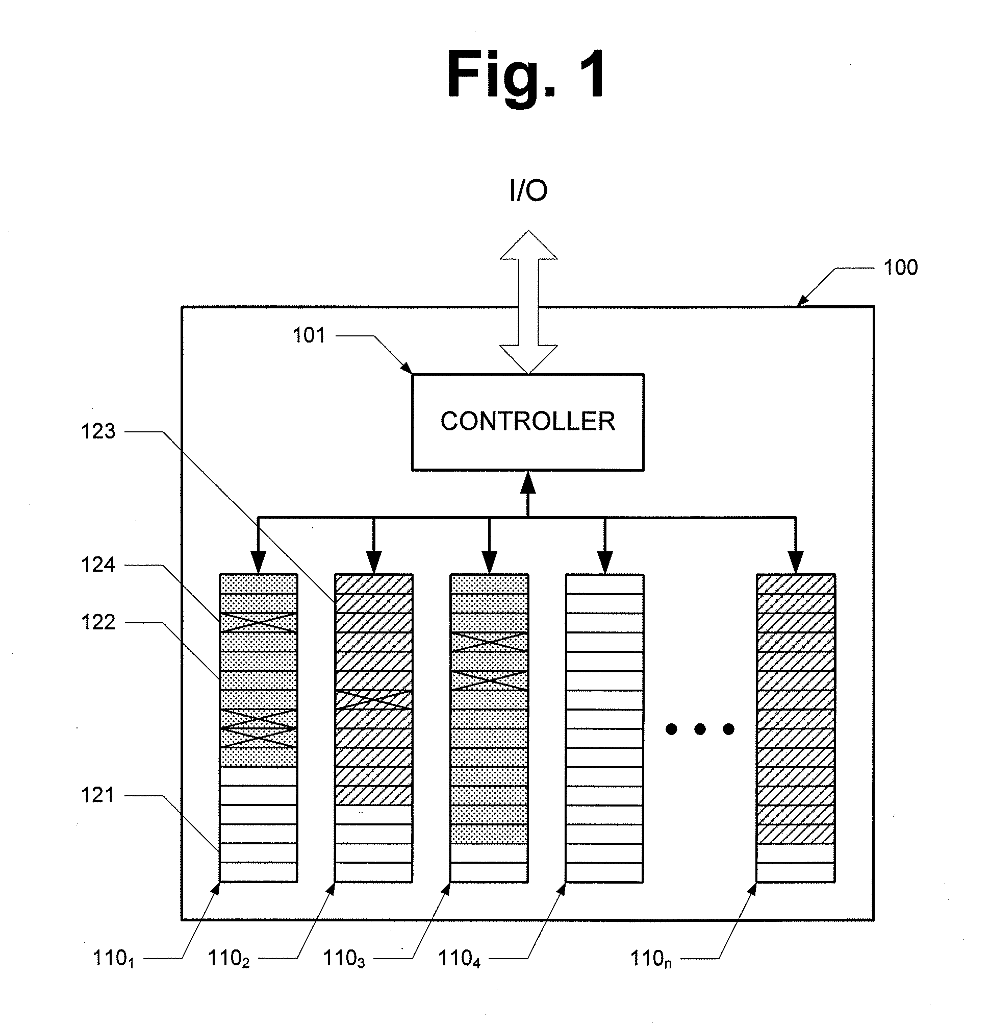
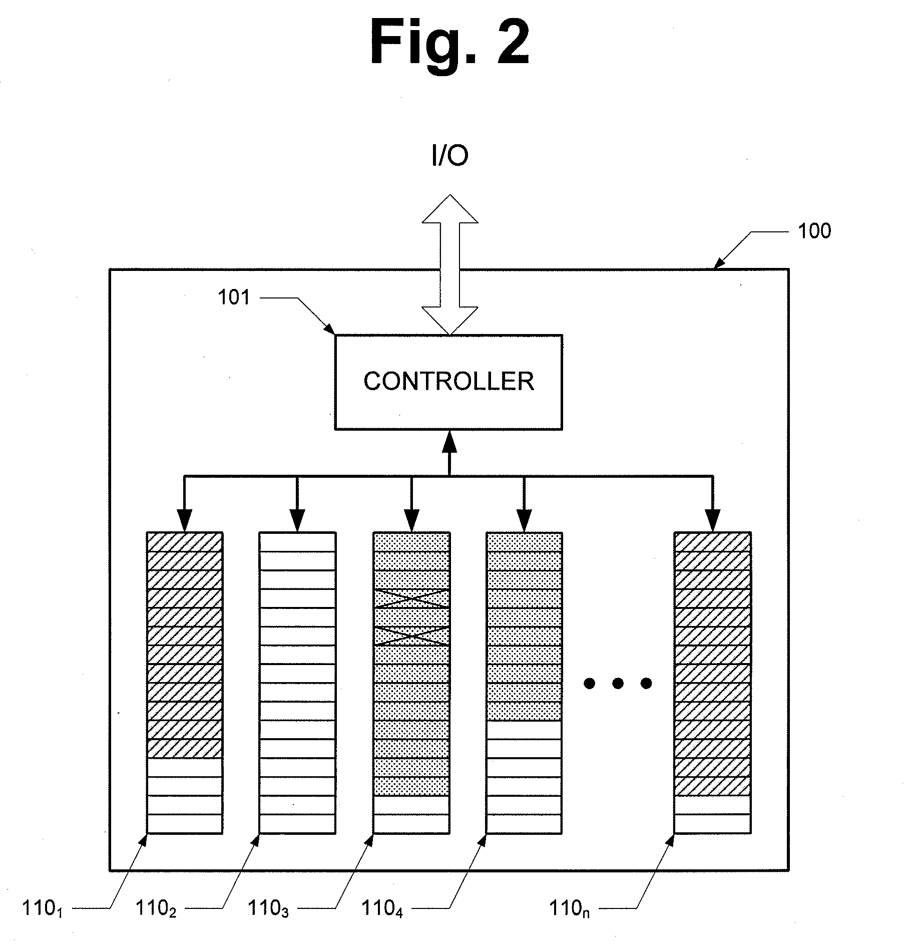
[0019]Referring to FIG. 1, a block diagram of a flash storage device according to one aspect of the subject disclosure is depicted. Flash storage device 100 includes a controller 101 and a number of data blocks 1101, 1102, 1103, 1104 . . . 110n. While the term “data block” is used throughout the description, it will be understood by those of skill in the art that the term data block is frequently used interchangeably with the term “memory block” in the art. Each data block has a plurality of data segments for storing data. In the present exemplary flash s...


PUM


Abstract

A method of wear leveling in a flash storage device comprising a plurality of data blocks is provided. The method comprises the steps of detecting a data error in a read of dynamic data from a first data segment of a first data block of the plurality of data blocks, correcting the data error, and moving the dynamic data from the first data segment to a second data segment in a second one of the plurality of data blocks.

Description

CROSS-REFERENCE TO RELATED APPLICATION[0001]The present application claims the benefit of priority under 35 U.S.C. §119 from U.S. Provisional Patent Application Ser. No. 61 / 075,709, entitled “SOLID STATE DEVICE,” filed on Jun. 25, 2008, the disclosure of which is hereby incorporated by reference in its entirety for all purposes.FIELD OF THE INVENTION[0002]The present invention relates to flash storage devices and, in particular, relates to improved wear leveling in flash storage devices.BACKGROUND OF THE INVENTION[0003]Flash memory is an improved form of Electrically-Erasable Programmable Read-Only Memory (EEPROM). Traditional EEPROM devices are only capable of erasing or writing one memory location at a time. In contrast, flash memory allows multiple memory locations to be erased or written in one programming operation. Flash memory can thus operate at higher effective speeds than traditional EEPROM.[0004]Flash memory enjoys a number of advantages over other storage devices. It gen...

Claims


Application Information

Patent Timeline
IPC IPC(8): G06F11/20G06F12/00G06F12/02
CPCG06F11/1441G06F3/0613G06F3/0659G06F3/0688
Inventor MOSHAYEDI, MARK
Owner HGST TECH SANTA ANA
Why Eureka
Try Eureka