Control moment gyroscope

a control moment and gyroscope technology, applied in the field of rotating inertial devices, can solve the problems of low bandwidth performance regarding the transmission of torque to the spacecraft, the inability of high-speed rotors to enable the reduction of the dimensions of tma or sma, and the addition of undesirable weight and volume to cmgs

Active Publication Date: 2010-01-07
HONEYWELL INT INC
View PDF12 Cites 23 Cited by
  • Summary
  • Abstract
  • Description
  • Claims
  • Application Information

AI Technical Summary

Benefits of technology

[0006]A control moment gyroscope (CMG) is provided for deployment on a spacecraft. The CMG includes a stator housing, an inner gimbal assembly disposed in the stator housing, and a torque motor coupled

Problems solved by technology

However, high speed rotors do not enable the dimensions of the TMA or the SMA to be reduced.
Consequently, the TMA and, to a lesser extent, the SMA may add undesirable weight and volume to CMGs employing high speed rotors as well as smaller CMGs with lower torque requirements.
As a result, conventional CMG

Method used


Image

  • Control moment gyroscope
  • Control moment gyroscope
  • Control moment gyroscope

Examples


Embodiment Construction

[0011]The following Detailed Description is merely exemplary in nature and is not intended to limit the invention or the application and uses of the invention. Furthermore, there is no intention to be bound by any theory presented in the preceding Background or the following Detailed Description.

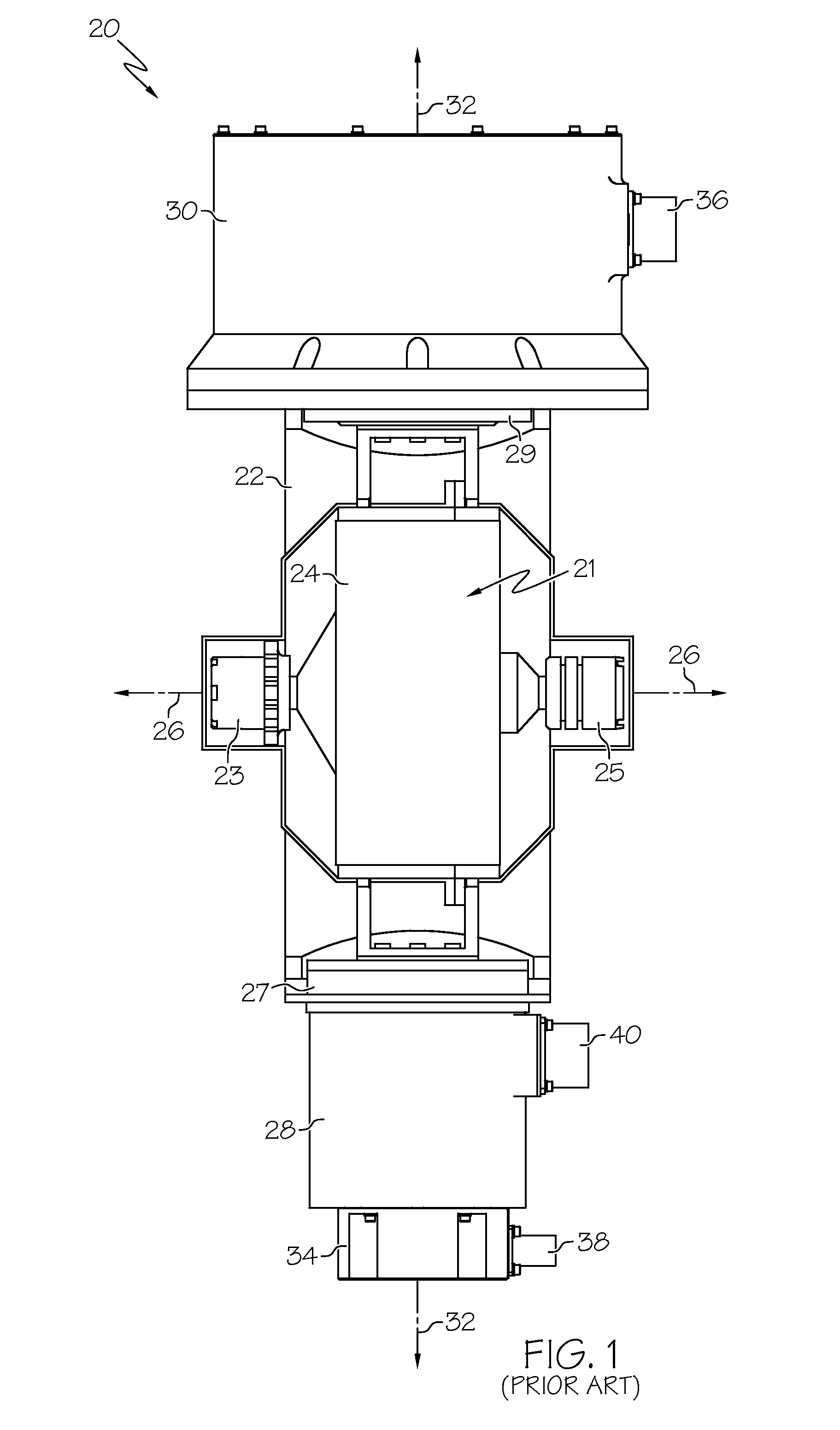
[0012]FIG. 1 is a plan view of a conventional control moment gyroscope (CMG) 20 suitable for deployment on a spacecraft, such as a satellite. CMG 20 is comprised of a stator housing 22 (e.g., a basering structure) that supports an inner gimbal assembly (IGA) 21. In this case, IGA 21 contains a high speed rotor 24 that is rotationally coupled to the housing of IGA 21 via first and second spin bearings 23 and 25. High speed rotor 24 may be rotated about a spin axis 26 by a spin motor (not shown) disposed within IGA 21. A signal module assembly (SMA) 28 and a torque module assembly (TMA) 30 are mounted to opposite end portions of stator housing 22 and IGA 21 such that IGA 21 is disposed between...


PUM


Abstract

A control moment gyroscope (CMG) is provided for deployment on a spacecraft. The CMG includes a stator housing, an inner gimbal assembly disposed in the stator housing, and a torque motor coupled to the stator housing and at least partially disposed around an intermediate portion of the inner gimbal assembly. The torque motor is configured to rotate the inner gimbal assembly about a gimbal axis.

Description

TECHNICAL FIELD[0001]The present invention relates generally to rotating inertial devices and, more particularly, to a control moment gyroscope including an improved momentum control system configuration that eliminates the need for a discrete torque module assembly.BACKGROUND[0002]Control moment gyroscopes (CMGs) are commonly employed in satellite attitude control systems. A generalized CMG comprises an inner gimbal assembly (IGA) supported by a stator housing (e.g., basering structure). The IGA includes a rotor assembly comprised of an inertial element (e.g., a ring or cylinder) coupled to a shaft. A spin bearing is disposed at each end of the shaft to permit the rotor to rotate about a spin axis. A spin motor couples to and drives the rotor thus allowing momentum to be stored. A torque module assembly (TMA) is mounted to a first end portion of the stator housing, and a signal module assembly (SMA) is mounted to the second end portion of the stator housing opposite the TMA. The TM...

Claims


Application Information

Patent Timeline
IPC IPC(8): G01C19/04
CPCB64G1/286Y10T74/1229Y10T74/1282Y10T74/1254
Inventor STEVENS, CARLOS J.FISKE, STEPHEN E.
Owner HONEYWELL INT INC
Why Eureka
Try Eureka