[0017]According to the first aspect <1> of the present invention, in the decoration region, the patterns of the pattern portion are formed by ridges and, among the marks of the mark portion, at least the mark having the widest extending width in the tire radial direction (i.e. the most important mark which should be the most distinctive among the marks) is constituted of a flat surface in parallel to a sidewall surface or a plurality of the flat surfaces in combination such that the highest height of the flat surface / surfaces with respect to the sidewall
surface level is higher than the highest height of the pattern portion. Accordingly, the most important mark can be distinguished from the pattern portion in the two points that: the former is not formed by ridges; and the highest height of the former is significantly higher than the latter or the pattern portion, whereby the most important mark is clearly distinguished from the pattern portion and
visibility of the most important mark can be enhanced. Further, the visibility of the most important mark is not affected wherever the most important mark is arranged in the pattern portion, whereby degree of freedom in arranging marks can be significantly enhanced. Yet further, since the pattern portion is formed as a combination of the first
ridge group and the second ridge group, the design properties of the pattern portion can be improved.
[0018]According to the second aspect <2> of the present invention, the pattern portion is constituted of a region where only the first ridge group exists and another region where the first ridge group and the second ridge group coexist. As a result, the patterns of the pattern portion are formed by two regions which apparently differ from each other in visibility, whereby the design properties of the pattern portion can be further improved.
[0019]According to the third aspect of the present invention, since the highest height of ridges of the second ridge group is not higher than the highest height of ridges of the first ridge group, the design properties of the pattern portion can have good diversity.
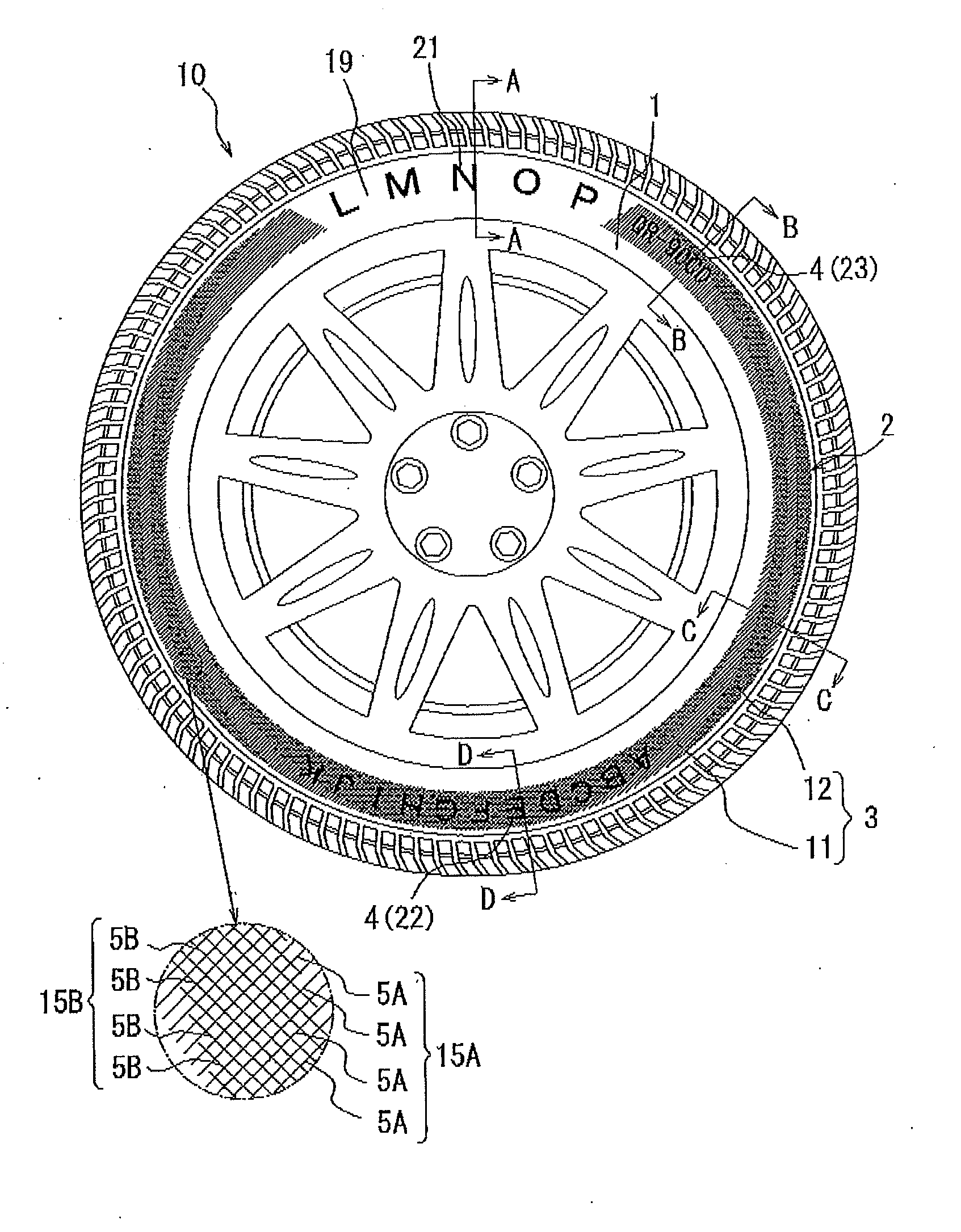
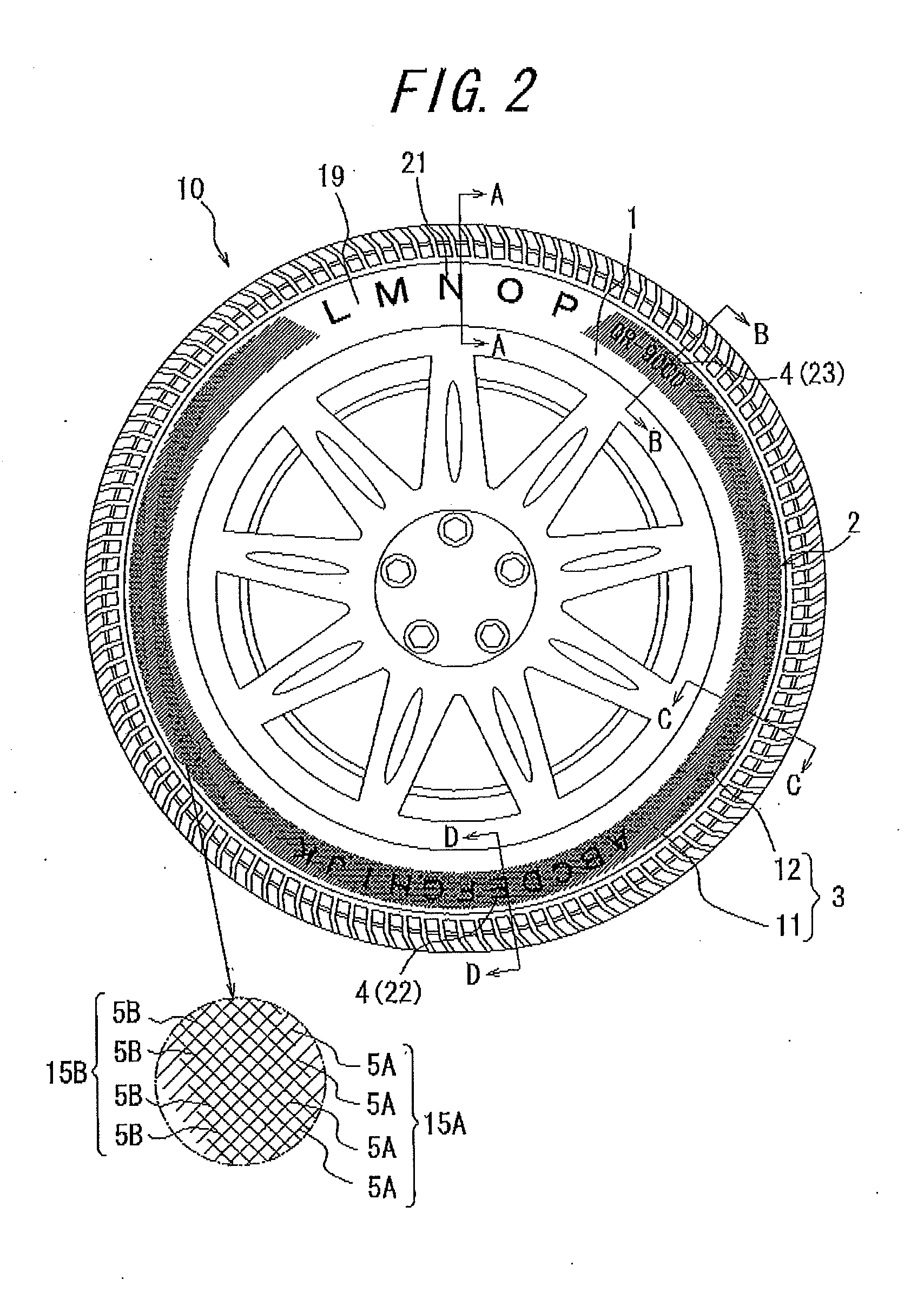
[0020]According to the fourth aspect of the present invention, a boundary, between the region where the first ridge group and the second ridge group coexist and the region where only the first ridge group exists, intersects with the mark having the widest extending width in the tire radial direction. As a result, the sidewall portion can be designed to have three-dimensional visibility, whereby the sidewall portion can have appearance of luxury and high-quality.
[0021]According to the fifth aspect of the present invention, the mark portion of the decoration region is constituted of marks of plural types and at least one type of the marks, which is not the mark having the widest extending width in the tire radial direction, is formed by the region where the first ridge group and the second ridge group coexist. As a result, a mark which is less important than other marks can be formed by a structure similar to that of the pattern portion, whereby visibilities of other more important marks can be relatively enhanced.
[0022]According to the sixth aspect of the present invention, the intersecting angle on the
acute angle side formed between the ridges of the first ridge group and the ridges of the second ridge group in the region where the first ridge group and the second ridge group coexist is in the range of 45 to 90°. As a result, the region where only the first ridge group exist can be more clearly distinguished from the region where the first ridge group and the second ridge group coexist, whereby the design properties of the pattern can be further improved.

