Method to detect casing point in a well from resistivity ahead of the bit
a resistivity and wellbore technology, applied in the direction of survey, wellbore/well accessories, sealing/packing, etc., can solve the problems of not disclosing or suggesting the use of resistivity in front of the bit measurement in the wellbore, and achieving the effect of enhancing recovery
- Summary
- Abstract
- Description
- Claims
- Application Information
AI Technical Summary
Benefits of technology
Problems solved by technology
Method used
Image
Examples
embodiment 300
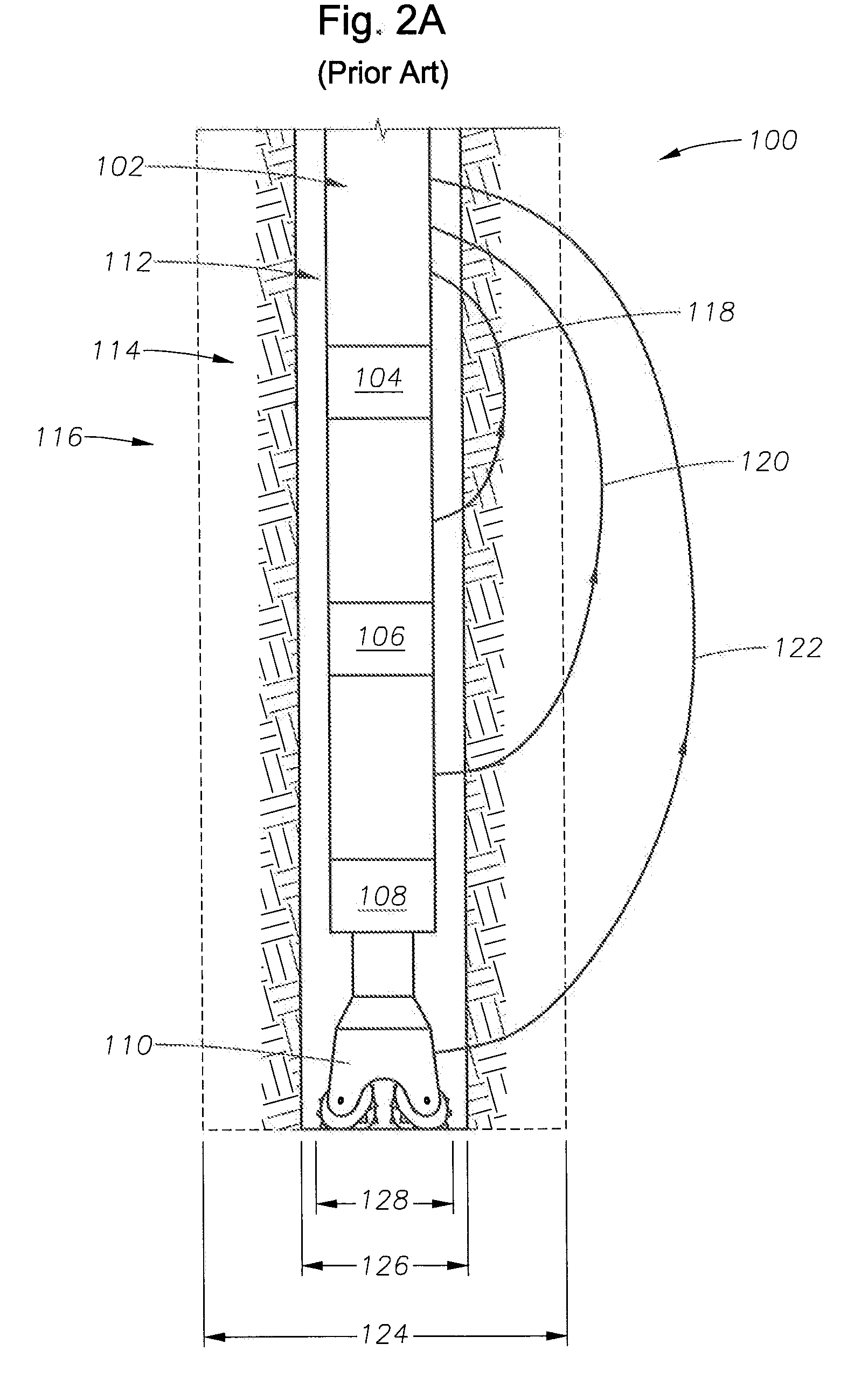
[0039]In accordance with the present disclosure, as illustrated inFIG. 3A, the lower toroid 130 is placed down at the tip of the bit 110, or very near thereto. In such embodiments the rock being investigated will be increasingly moved forward ahead of the bit 110, as illustrated schematically in FIG. 3B. While this may seem to be a subtle change, the result is much greater ability to focus the resistivity measurements in front of the drill, and allow one or more casing points to be identified in one or more uncased intervals of the wellbore prior to the bit entering the region that appears in need of casing. FIG. 3C illustrates a method in accordance with this disclosure, illustrating schematically in embodiment 300 including an offset well 112a from which resistivity data has been previously gathered using conventional methods from a region of interest 90 in the formation previously drilled using drillstring 101 and drill bit 110 (both illustrated in phantom in FIG. 3C). An uncased...
embodiment 800
[0045]FIG. 8 illustrates an embodiment 800 modified to focus energy in front of the bit and measure the formation resistivity ahead of the drill bit. Rather than sensing an oil / water contact, the reflected waves 85 would be reflected off of the top of a region of interest 90, containing perhaps, but not necessarily, hydrocarbons.
[0046]In accordance with the present disclosure, a primary interest lies in using resistivity measurements gathered by one or more conventional wireline or LWD methods, or one of the methods and apparatus described above to obtain resistivity measurements in front of the drill bit while drilling one or more offset wells, to identify casing points in an uncased interval of a well being drilled but prior to the bit entering the formation. The skilled operator or well designer will determine which resistivity method and apparatus is best suited for a particular offset well and formation to achieve the highest efficiency without undue experimentation.
[0047]The i...
embodiment 900
[0056]FIG. 9 illustrates one method embodiment 900 of the present disclosure in flowchart form. Assuming resistivity in front of the drill bit is already available from one or more offset wells, first, as indicated in box 902, the drilling supervisor, probably in conjunction with the mud engineer, geologist or other person in charge would choose initial drilling mud for drilling an uncased interval of the well, and the driller would choose the drill bit for drilling the uncased interval of the well. Optionally, apparatus for determining resistivity in front of the drill bit may be selected and installed in the drill string, either on-site or at a site removed from the well. In box 904, the drilling is then begun, drilling toward a region of interest at a known azimuth and dip angle using the selected drilling mud and drill bit (and selected resistivity apparatus, in some embodiments). Box 906, resistivity data in front of the offset bit is used while drilling toward the region of in...
PUM
 Abstract
Description
Claims
Application Information
 - R&D
- Intellectual Property
- Life Sciences
- Materials
- Tech Scout
- Unparalleled Data Quality
- Higher Quality Content
- 60% Fewer Hallucinations
Browse by: Latest US Patents, China's latest patents, Technical Efficacy Thesaurus, Application Domain, Technology Topic, Popular Technical Reports.
© 2025 PatSnap. All rights reserved.Legal|Privacy policy|Modern Slavery Act Transparency Statement|Sitemap|About US| Contact US: help@patsnap.com


