
Maxim electron scatter chamber

a technology of electron scattering and chamber, applied in the field of sterilization or purification of objects, can solve the problems of reducing flavor, reducing quality, and damaging food products

Inactive Publication Date: 2010-01-07
TEXAS A&M UNIVERSITY
View PDF6 Cites 4 Cited by
  • Summary
  • Abstract
  • Description
  • Claims
  • Application Information

AI Technical Summary

Benefits of technology

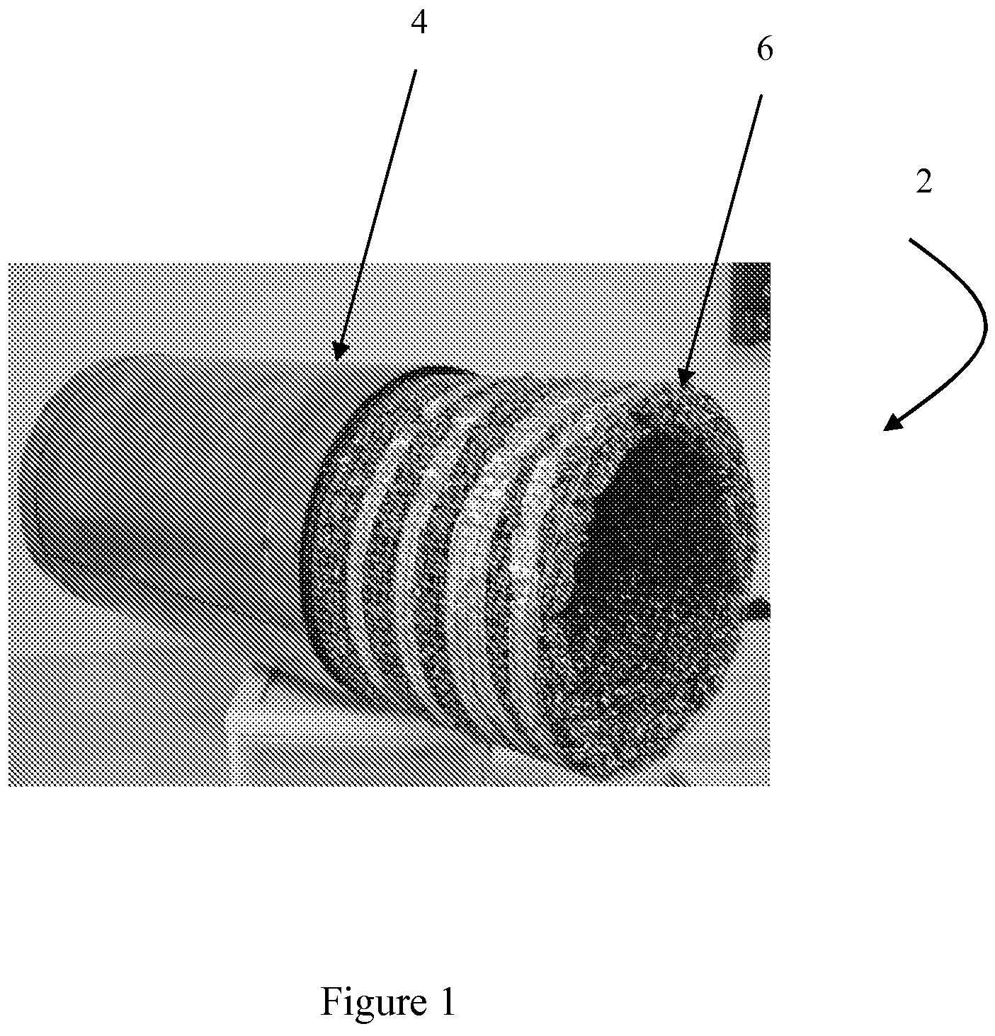
[0011]The present invention provides methods and apparatus to apply electron beam irradiation on geometrically irregular surfaces. Electron scattering is normally perceived as a disadvantage of e-beam irradiation; however, the present invention demonstrated surprising and unexpected capability of generating energy doses that produce the greatest bacterial reduction without affecting product quality for round and / or irregular surfaces of one ore more object.
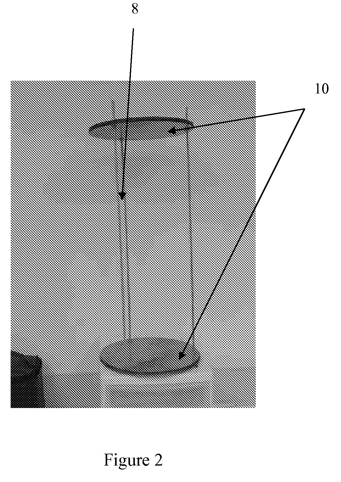
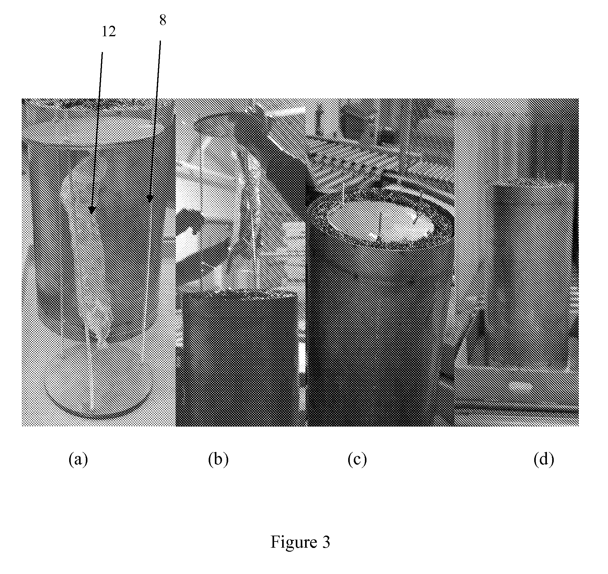
[0015]In another aspect, the present invention includes methods to pasteurize at least one target. The method includes placing at least one target in a chamber having a scattering space; generating an infinite number of linear electron beams using at least one linear high energy (10 MeV) electron accelerator; to contact a mesh (or any other scattering device) positioned in the scattering space; scattering one or more of the linear electron beam in random linear directions, thereby generating an electron cloud consisting of electrons of various energy levels; and allowing the energy cloud to engulf the target with sufficient number of impacts to accumulate dose and for sufficient amount of time to achieve the desired dose accumulation for pasteurization / sterilization. The method can also include an attenuating device for one or more of the linear electron beam using at least one energy attenuator, where the direct linear high energy electron beam is attenuated to a level where the final accumulated dose will be congruent with the desired / achieved dose levels throughout the target surface.

Problems solved by technology

Unfortunately, methods involving high heat such as this can sometimes damage the food product and reduce its quality.
For example, flavors may be reduced, desirable colors may be lost, and nutritional value may diminish.
However, almost all of the above mention references suffer from multiple drawbacks.
For example, most existing technologies cannot deliver uniform dose of energy.
When the energy dose is too high, the object (e.g., food products) may be damaged, and if the dose is too low, insufficient sterilization can occur.
Furthermore, shape of the object causes additional problems because irregular shapes (e.g., round or that of a carcass) contribute more towards non-uniform energy dose distributions by displaying hard to reach angles for a typically irradiation to reach.

Method used


Image

  • Maxim electron scatter chamber
  • Maxim electron scatter chamber
  • Maxim electron scatter chamber

Examples


Embodiment Construction

[0022]While the making and using of various embodiments of the present invention are discussed in detail below, it should be appreciated that the present invention provides many applicable inventive concepts that can be embodied in a wide variety of specific contexts. The specific embodiments discussed herein are merely illustrative of certain embodiments, and are not intended to limit the materials / designs and ways to make and use the invention and they are not to limit the scope of the invention.

[0023]To facilitate the understanding of this invention, a number of terms are defined below. Terms defined herein have meanings as commonly understood by a person of ordinary skill in the areas relevant to the present invention. Terms such as “a”, “an” and “the” are not intended to refer to only a singular entity, but include the general class of which a specific example may be used for illustration. The terminology herein is used to describe specific embodiments of the invention, but the...


PUM


Abstract

The present invention includes a system, methods and apparatus for sterilization of an object (e.g., food products). The present invention takes advantage of the electron scatter that occurs when electron beam is applied onto a surface. The present invention is capable of treating irregular surfaces (e.g., carcasses, spherical / round surfaces) or any type of surface where complete penetration is not needed or desired.

Description

CROSS-REFERENCE TO RELATED APPLICATIONS[0001]This application claims priority to U.S. Provisional Application Ser. No. 61 / 077,229, filed Jul. 1, 2008, the entire contents of which are incorporated herein by reference.TECHNICAL FIELD OF THE INVENTION[0002]The present invention relates in general to the field of pasteurization or sterilization of objects and, more particularly, to methods and apparatus designed to pasteurize objects (e.g., food products) without significantly degrading characteristics of the object.BACKGROUND OF THE INVENTION[0003]Various methods of pasteurizing food products have been developed over the years. Most of the commercial processes are for pasteurizing liquid / semi-liquid food products, such as juices, pastes, relishes, sauces, and other foods, involve heating the product to a process temperature above certain temperature and holding it for a scheduled process time and then rapidly cooling the product prior to packaging. Unfortunately, methods involving hig...

Claims


Application Information

Patent Timeline
IPC IPC(8): G01N23/00
CPCA23L3/26
Inventor MAXIM, JOSEPH E.NEAL, JACK A.CASTILLO, ALEJANDRO
Owner TEXAS A&M UNIVERSITY
Learn More