Light emitting diode illuminating apparatus with same-type light emitting diodes

a technology of light-emitting diodes and illuminating apparatuses, which is applied in the direction of lighting and heating apparatuses, solid-state devices, semiconductor devices for light sources, etc., can solve the problem of liable unsatisfactory color temperature stability

Inactive Publication Date: 2010-01-07
ADVANCED OPTOELECTRONICS TECH
View PDF9 Cites 47 Cited by
  • Summary
  • Abstract
  • Description
  • Claims
  • Application Information

AI Technical Summary

Problems solved by technology

In addition, the stability of the color temperature is liable to be unsatisfactory with changes in the elevated temperatures of the blue LED chip and the red LED chip.

Method used


Image

  • Light emitting diode illuminating apparatus with same-type light emitting diodes
  • Light emitting diode illuminating apparatus with same-type light emitting diodes
  • Light emitting diode illuminating apparatus with same-type light emitting diodes

Examples


first embodiment

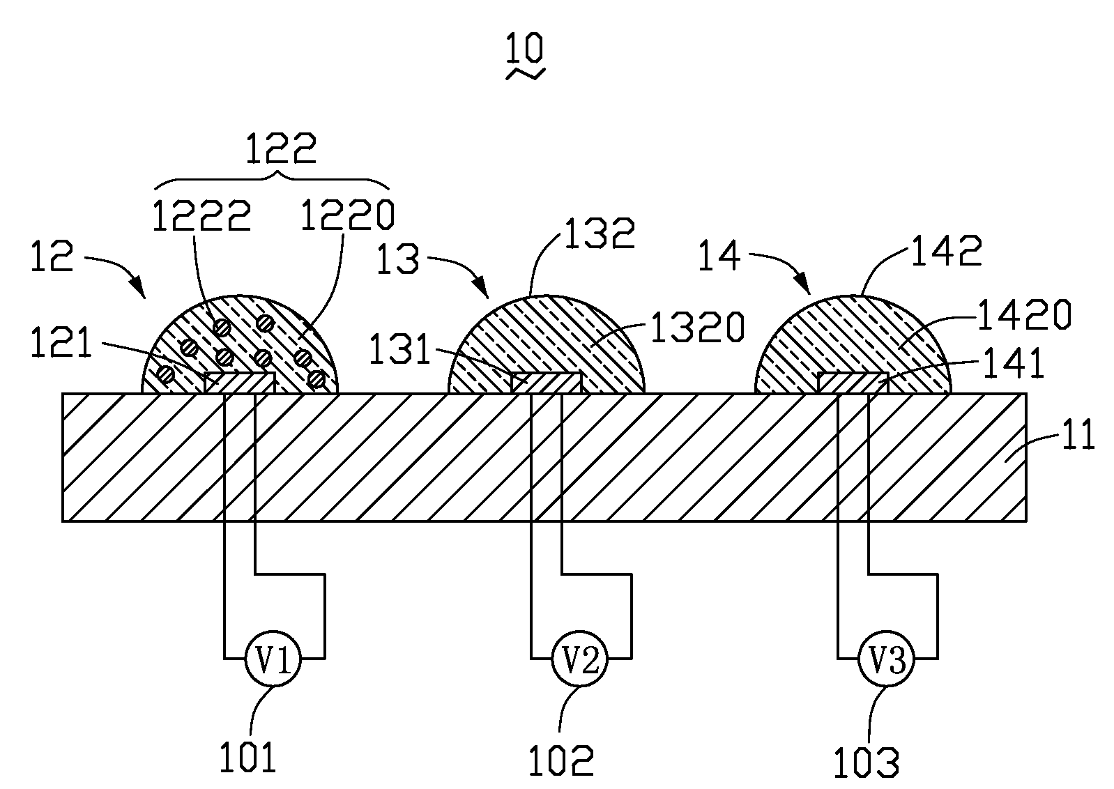
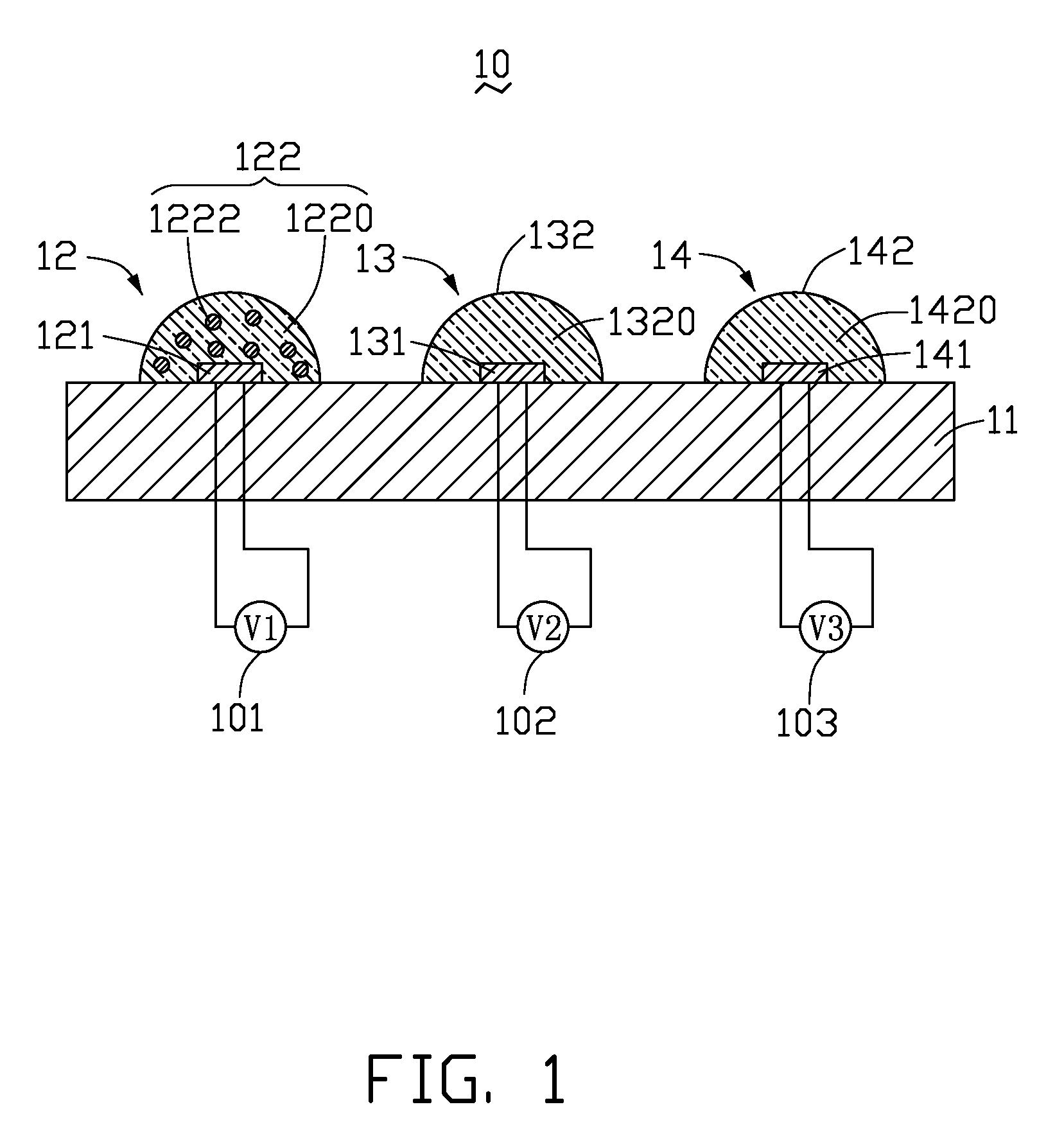
[0016]Referring to FIG. 1, a light emitting diode illuminating apparatus 10 includes a substrate 11, a first lighting element 12, a second lighting element 13, and a third lighting element 14.

[0017]The first lighting element 12, the second lighting element 13, and the third lighting element 14 are positioned on the substrate 11 in a juxtaposed manner. The substrate 11 may be connected to a power source (not shown) to supply electric current to the first lighting element 12, the second lighting element 13, and the third lighting element 14. In addition, heat generated from the first lighting element 12, the second lighting element 13, and the third lighting element 14 can be conducted out of the light emitting diode illuminating apparatus 10 through the substrate 11. The substrate 11 may be made of metal such as copper or aluminum, ceramic such as silicon nitride, aluminum oxide, or beryllium oxide, or silicon. It can be understood that the substrate 11 may be ceramic aluminum substr...

seventh embodiment

[0041]Referring to FIG. 7, a light emitting diode illuminating apparatus 70 includes a substrate 71, a first lighting element 72, and a second lighting element 73.

[0042]The substrate 71 defines a first recess 710 and a second recess 712. Each of the first recess 710 and the second recess 712 is truncated cone shaped, with a diameter of the truncated cone gradually decreases from an exposed surface of the substrate 71. The first and second recesses 710, 712 are located in a juxtaposed manner.

[0043]The first lighting element 72 includes a first LED chip 721, and a first filling layer 722 encapsulating the first LED chip 721. The second lighting element 73 includes a second LED chip 731, and a second filling layer 732 encapsulating the second LED chip 731. The first LED chip 721 and the second LED chip 731 are positioned at bottoms of the first recess 710 and the second recess 712, respectively, and are electrically connected to the substrate 71. The first filling layer 722 and the sec...


PUM


Abstract

A light emitting diode illuminating apparatus for emitting colorful light includes a substrate, a first lighting element, a second lighting element, a third lighting element. The first, second and third lighting elements are juxtaposed at the substrate. The first lighting element includes a first LED chip, and a first filling layer encapsulating it. The first filling layer includes red phosphor generally evenly doped therein. The second lighting element includes a second LED chip and a second filling layer encapsulating it. The third lighting element includes a third LED chip and a third filling layer encapsulating it. All of the first, the second and the third LED chips are the same kind of LED chip selected from the group consisting of GaN LED chips, AlGaN LED chips and InGaN LED chips. Light emitting from the filling layers are capable of mixing to produce light of a uniform color.

Description

BACKGROUND[0001]1. Technical Field[0002]The disclosure generally relates to solid-state illuminating apparatuses, and particularly, to a light emitting diode illuminating apparatus having an improved color temperature stability of the emitting light.[0003]2. Description of Related Art[0004]Light emitting diodes (LEDs) as solid-state illuminating apparatuses are widely used in illumination applications. LEDs are promising candidates to substitute conventional fluorescent lamps, due to their high brightness, long service lifetime, and wide color gamut. These and related issues are discussed in an article entitled “Solid-State Lighting: Toward Superior Illumination” by Michael S. Shur et al., published in Proceedings of the IEEE, Vol. 93, No. 10, in October 2005.[0005]Generally, an LED lighting source is expected to have a high color rendering index (CRI), typically as high as CRI>90. A typical LED with a high CRI includes a blue LED chip, a red LED chip, and an encapsulant encapsul...

Claims


Application Information

Patent Timeline
Patent Type & Authority Applications(United States)
IPC IPC(8): H01L33/00
CPCF21K9/00H01L33/50H01L25/0753H01L2924/0002H01L2924/00
Inventor CHANG, CHUNG-MINHSU, CHIH-PENGWANG, CHUN-WEI
Owner ADVANCED OPTOELECTRONICS TECH
Why Eureka
Try Eureka