Air-Damped Engine Mount

a technology for engine mounts and mounts, applied in the direction of machine supports, shock absorbers, jet propulsion mountings, etc., can solve the problems of insufficient absorption of vibration and noise, complicated fabrication process, and considerable cost, and achieve the effect of enhancing the effect of damping vibration in the engine, and increasing the flow resistance against air

Inactive Publication Date: 2010-01-07
HYUNDAI MOTOR CO LTD +1
View PDF10 Cites 11 Cited by
  • Summary
  • Abstract
  • Description
  • Claims
  • Application Information

AI Technical Summary

Benefits of technology

[0022]According to various aspects of the present invention, the air track capable of increasing flow resistance against air is formed inside the core boss coupling with an engine, such that increased flow resistance against air enhances an effect of damping vibration in the engine, the air track is not clogged ensuring a normal operation even if moisture on the bottom of the damping chamber is frozen, and characteristics of damping vibration in the engine can be easily adjusted when necessary.

Problems solved by technology

The rubber engine mount made of solid rubber consists of a small number of parts, leading to merits such as a simple fabrication process and a cheap cost.
However, the problems of the rubber engine mount are that it may not sufficiently absorb vibration and noise due to poor damping efficiency.
However, the fluid-filled engine mount have problems such as a complicated fabrication process and a considerably expensive cost since a fluid-sealing structure is required.
However, in the air-damped engine mount constructed as above, the flow resistance against the entering and exiting air is very small due to direct communication with the outside through the air hole 41 and thereby the effect of damping the vibration in the engine is not sufficient.
In addition, the air hole 41 may be clogged by impurities when the engine is running or be clogged with frozen moisture in the winter.
In both cases, the air-damped engine mount fails to properly reduce vibration in the engine.

Method used


Image

  • Air-Damped Engine Mount
  • Air-Damped Engine Mount
  • Air-Damped Engine Mount

Examples


Embodiment Construction

[0027]Reference will now be made in detail to various embodiments of the present invention(s), examples of which are illustrated in the accompanying drawings and described below. While the invention(s) will be described in conjunction with exemplary embodiments, it will be understood that present description is not intended to limit the invention(s) to those exemplary embodiments. On the contrary, the invention(s) is / are intended to cover not only the exemplary embodiments, but also various alternatives, modifications, equivalents and other embodiments, which may be included within the spirit and scope of the invention as defined by the appended claims.

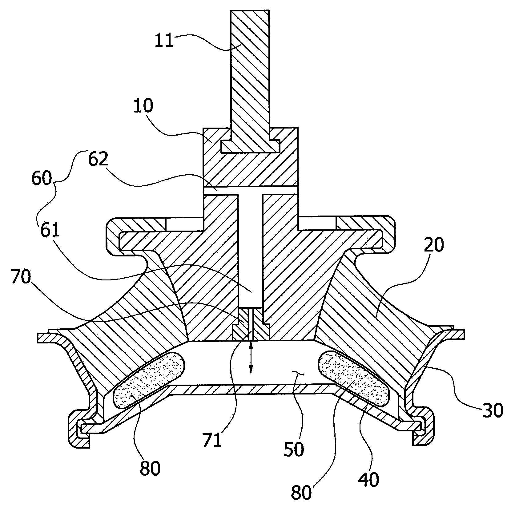
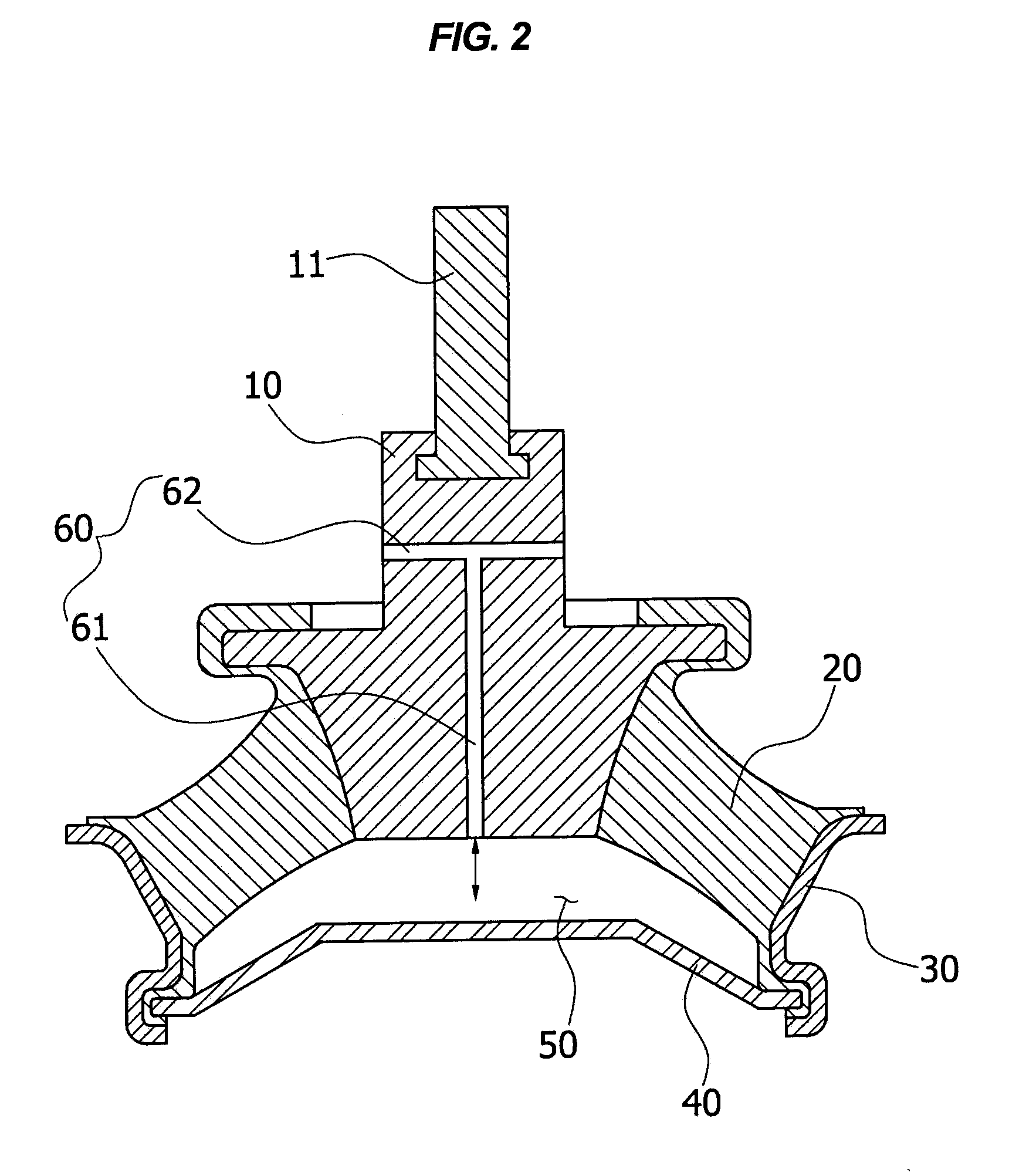
[0028]FIG. 2 is a schematic cross-sectional view illustrating the structure of an air-damped engine mount according to various exemplary embodiments of the present invention.

[0029]As shown in FIG. 2, the typical air-damped engine mount according to various exemplary embodiments of the present invention includes a core boss 10 coupling...


PUM


Abstract

An air-damped engine mount may include a core boss coupled with an engine of a vehicle, a main rubber coupled with the core boss and elastically supporting the core boss, a hollow main pipe tightly coupled with the main rubber and supporting the main rubber, and a cover plate tightly coupled with one end portion of the main pipe to form a damping chamber in a space between the cover plate and the main rubber, wherein the core boss defines at least an air track allowing the damping chamber to fluid-communicate with the outside therethrough such that vibration in the engine is damped by flow resistance against air passing through the air track.

Description

CROSS-REFERENCE TO RELATED APPLICATION[0001]The present application claims priority to Korean Patent Application Number 10-2008-0064057 filed on Jul. 2, 2008, the entire contents of which is incorporated herein for all purposes by this reference.BACKGROUND OF THE INVENTION[0002]1. Field of the Invention[0003]The present invention relates to an air-damped engine mount. More particularly, the present invention relates to an air-damped engine mount, in which an air track capable of increasing flow resistance against air is formed inside a core boss coupling with an engine, such that increased flow resistance against air enhances an effect of damping vibration in the engine, the air track is not clogged ensuring a normal operation even if moisture on the bottom of the damping chamber is frozen, and characteristics of damping vibration in the engine can be easily adjusted when necessary.[0004]2. Description of Related Art[0005]In general, an engine mount used for mounting an engine to a ...

Claims


Application Information

Patent Timeline
Patent Type & Authority Applications(United States)
IPC IPC(8): F16F9/00
CPCF16F2224/0225F16F13/20B60K5/12
Inventor KIM, JEONG HOONSHIN, HEAN JUNG
Owner HYUNDAI MOTOR CO LTD
Why Eureka
Try Eureka