Fluorescent lamp with adjustable color temperature

Inactive Publication Date: 2010-01-07
DELTA ELECTRONICS INC
View PDF6 Cites 1 Cited by
  • Summary
  • Abstract
  • Description
  • Claims
  • Application Information

AI Technical Summary

Benefits of technology

[0012]As mentioned above, the fluorescent lamp of the present invention utilizes two driving devices to independently control the lighting illuminations of at least two lighting elements, so that the color temperature of the light emitted therefrom can be adjusted.

Problems solved by technology

Thus, if the light source with different color temperature is needed, the light bulb must be changed, which causes inconveniences in usage.

Method used


Image

  • Fluorescent lamp with adjustable color temperature
  • Fluorescent lamp with adjustable color temperature
  • Fluorescent lamp with adjustable color temperature

Examples


Embodiment Construction

[0021]The present invention will be apparent from the following detailed description, which proceeds with reference to the accompanying drawings, wherein the same references relate to the same elements.

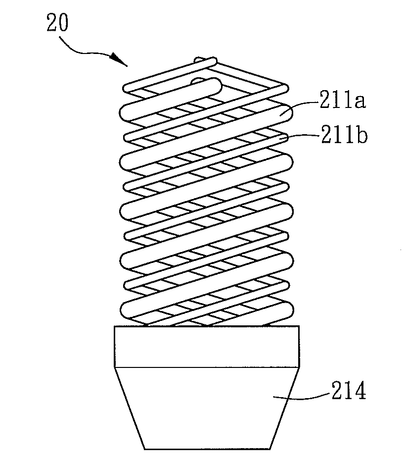
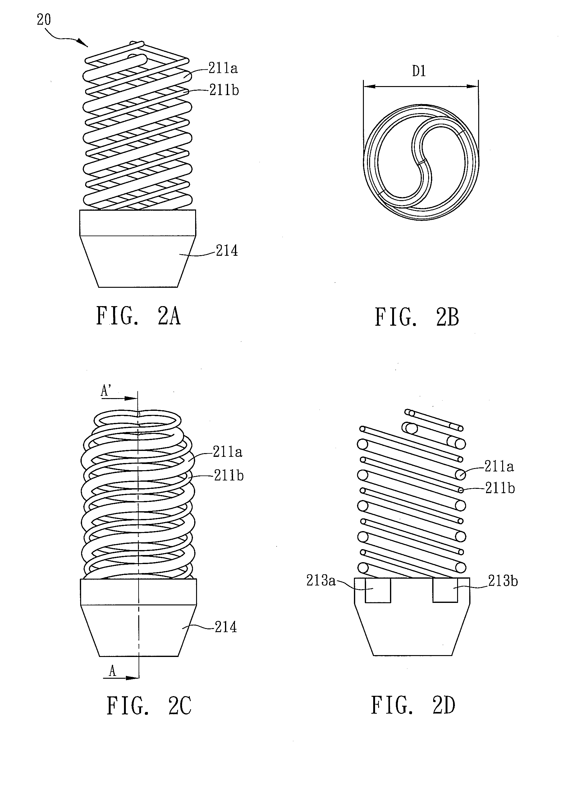
[0022]FIGS. 2A, 2B, 2C and 2D are schematic illustrations showing an aspect of a fluorescent lamp according to an embodiment of the present invention. FIG. 2A shows a front view of the fluorescent lamp, FIG. 2B shows a top view of the fluorescent lamp, FIG. 2C shows a side view of the fluorescent lamp, and FIG. 2D shows a sectional view along the line AA′ of FIG. 2C. Referring to FIG. 2A, a fluorescent lamp 20 includes a first lighting element 211a and a second lighting element 211b. The first and second lighting elements 211a, 211b are both made of a glass tube, which has a tube diameter ranging from 1.8 to 40 mm. The first and second lighting elements 211a, 211b have spiral structures with the same spiral cycle number and spiral diameter, and both of which are spirally interlaced wi...


PUM


Abstract

A fluorescent lamp includes at least two lighting elements, which emit lights with different color temperatures. In addition, the lighting illuminations of the lighting elements can be controlled by independent driving devices. Thus, the user can adjust the color temperature of the light emitted from the fluorescent lamp.

Description

CROSS REFERENCE TO RELATED APPLICATIONS[0001]This Non-provisional application claims priority under 35 U.S.C. §119(a) on Patent Application No(s). 097125155 filed in Taiwan, Republic of China on Jul. 4, 2008, the entire contents of which are hereby incorporated by reference.BACKGROUND OF THE INVENTION[0002]1. Field of Invention[0003]The present invention relates to a fluorescent lamp and, in particular, to a fluorescent lamp that can adjust the color temperature of the light emitted therefrom.[0004]2. Related Art[0005]Recently, the energy saving awareness has become one of the hottest topics. For example, the traditional incandescent light bulbs have been substituted by the energy saving light bulbs gradually. The energy saving light bulbs in the market usually has a base and a spiral hot cathode lamp installed on the base. The appearance of the energy saving light bulb is similar to that of the traditional incandescent light bulb so that the energy saving light bulb can be used in ...

Claims


Application Information

Patent Timeline
IPC IPC(8): H01J61/30
CPCH01J61/94H01J61/327
Inventor LIN, SHIH-HSIENLIN, MAW-CHUANPAN, KUNG-TUNGHUANG, MEI-HUEICHENG, WEI-CHUNG
Owner DELTA ELECTRONICS INC
Why Eureka
Try Eureka