
Active matrix display device

a display device and active matrix technology, applied in the direction of instruments, static indicating devices, etc., can solve the problems of increasing the density of the connection section which connects the output of the driver ic and the terminal of the panel, and the mounting of the shift register becomes more difficult, so as to reduce the number of outputs and reduce the number of stages of the shift register

Inactive Publication Date: 2010-01-07
GLOBAL OLED TECH
View PDF9 Cites 17 Cited by
  • Summary
  • Abstract
  • Description
  • Claims
  • Application Information

AI Technical Summary

Benefits of technology

"The present invention provides an active matrix display device that sequentially supplies data to pixels in a matrix to realize a display. The device includes a data driver and a selection driver. The selection driver generates a selection signal to control the reading of data from a data line to a pixel. The selection driver includes a selection signal generator and multiple selection switches connected to the generator. The selection signal generator sequentially outputs the selection signal to the multiple selection lines, and the selection switches sequentially switch on to connect the selection lines. This reduces the number of outputs of the selection signal outputting section and allows for the sequential supply of an output from a shift register to multiple gate lines. This reduces the number of stages of the shift register and simplifies the process of supplying data to the pixels in the display."

Problems solved by technology

When the size of the display panel is not changed although the number of pixels and lines are increased, the mounting area of the shift register becomes relatively small, and thus it becomes more difficult to mount the shift register.
When the shift register is to be provided as a driver IC (Integrated Circuit) provided separately from the circuit on the glass substrate, a density of a connection section which connects an output of the driver IC and a terminal of the panel is increased, and the connection becomes difficult.
In a case where no shift register is provided and a decoder which selects a line is provided, an increase in the number of lines results in an increased number of outputs, and a similar disadvantage occurs.

Method used


Image

  • Active matrix display device
  • Active matrix display device
  • Active matrix display device

Examples


Embodiment Construction

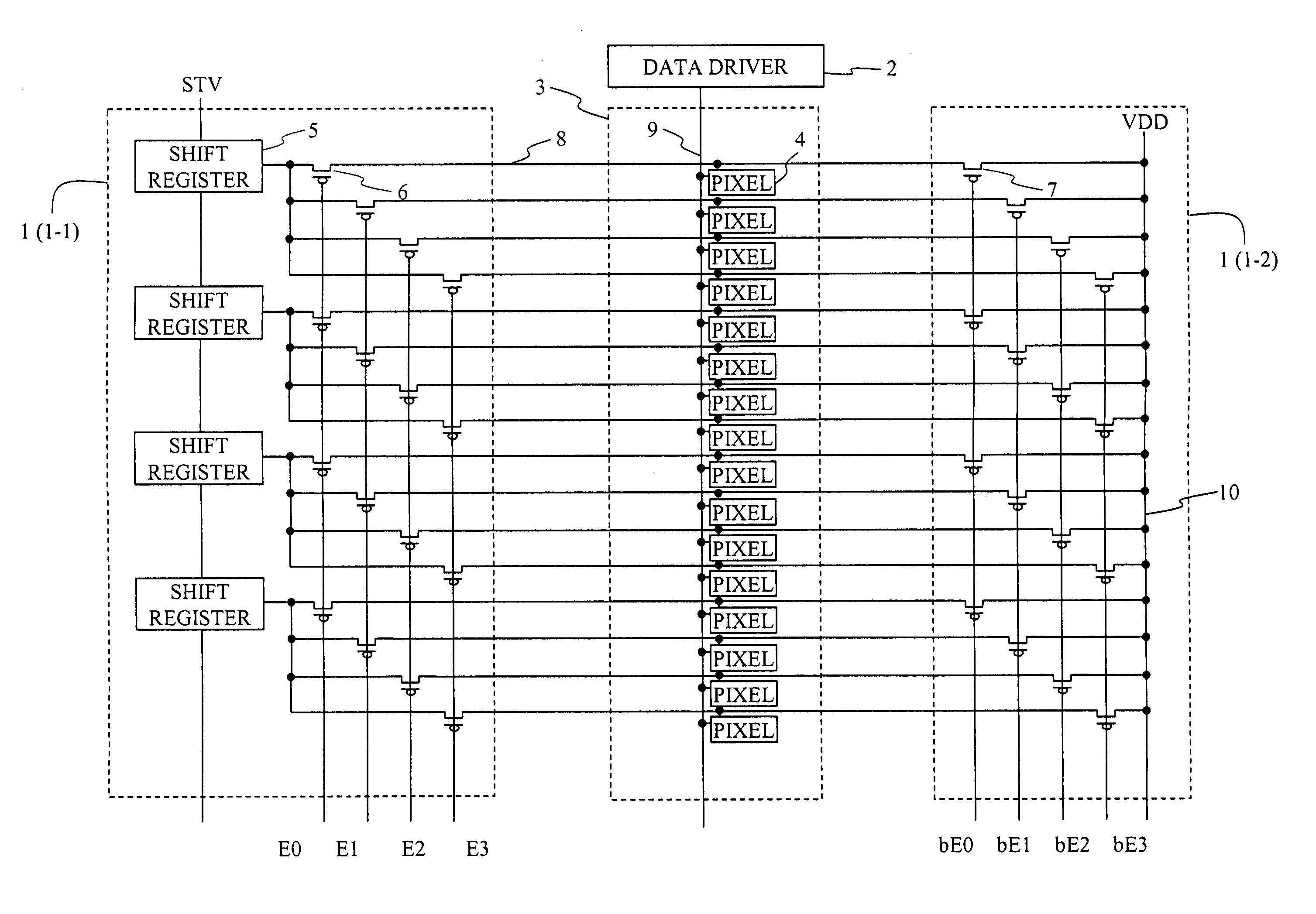
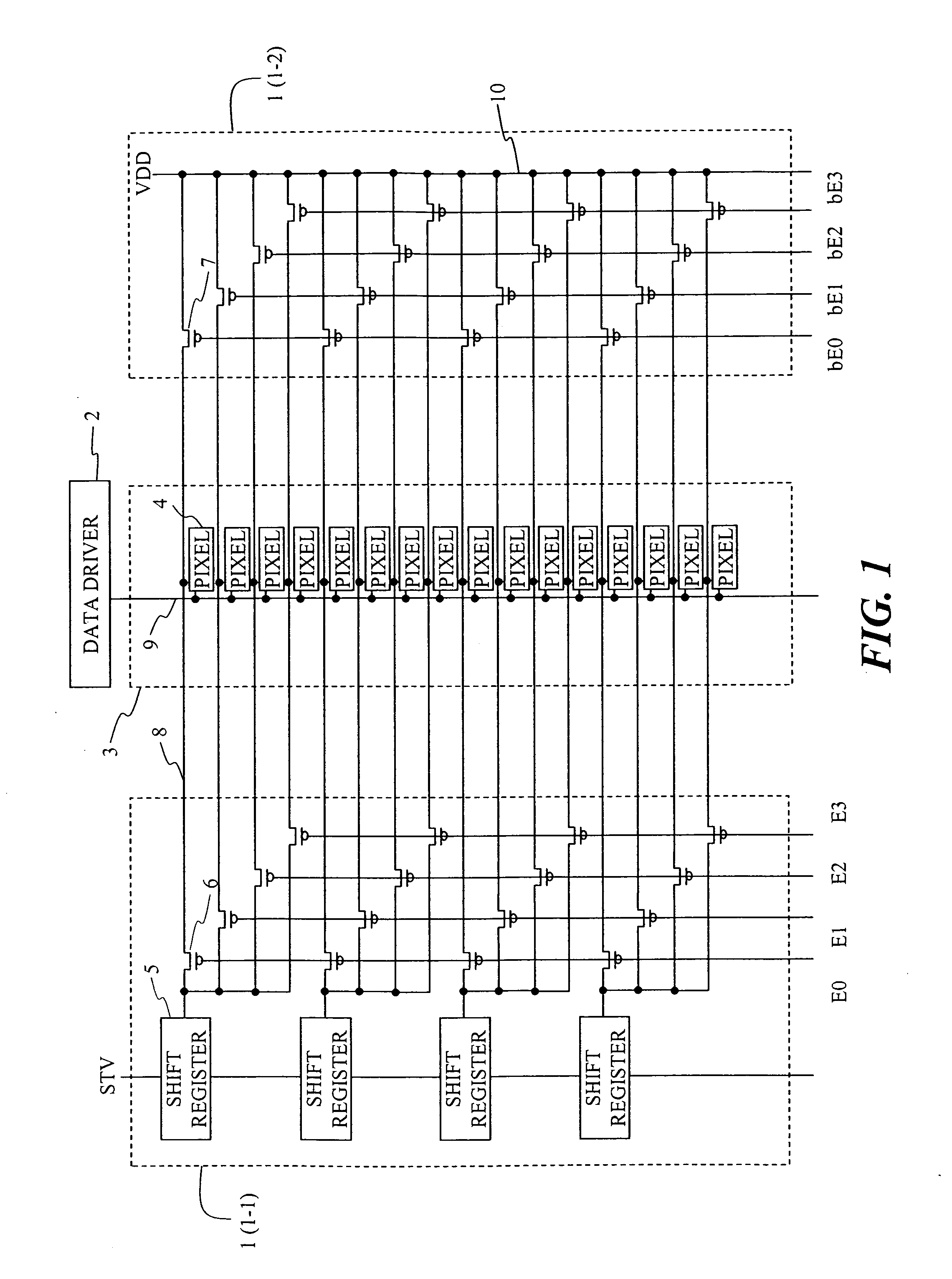
[0022]A preferred embodiment of the present invention will now be described referring to the drawings. FIG. 1 shows an example of an active matrix display device having a gate driver (selection driver) 1 of a preferred embodiment of the present invention.

[0023]A display device of FIG. 1 includes a gate driver 1 which is placed along a row direction and which controls selection of pixels for each horizontal line, a data driver 2 which controls supply of data to pixels of each column, and a pixel array 3 in which pixels 4 are arranged in a matrix form in column and row directions (only one column is shown in FIG. 1).

[0024]The gate driver 1 is functionally divided into a controller 1-1 which controls selection / non-selection of a gate line (selection line) 8 provided corresponding to each row of pixels and a retaining section 1-2 which retains non-selection of the gate line 8. The data driver 2 supplies a data signal corresponding to video data from the outside to a data line 9.

[0025]A ...


PUM


Abstract

A data driver supplies data to a data line provided corresponding to a pixel column. A selection driver sequentially supplies a selection signal to a selection line provided corresponding to a pixel row. The selection driver has a shift register which receives a supply of a shift clock and sequentially transfers a selection signal to a register of a plurality of stages, and a plurality of switches which are connected to outputs of the stages of the register of the shift register and control supply of a selection signal to plurality of selection lines. By sequentially switching a plurality of switches connected to the output of the register ON while a selection signal is output from one register of the shift register, data is supplied to pixels arranged in a matrix form to a display array.

Description

FIELD OF THE INVENTION[0001]The present invention relates to an active matrix display device in which data is supplied to pixels arranged in a matrix form and display is realized.BACKGROUND OF THE INVENTION[0002]In an active matrix display device, data corresponding to each of a plurality of pixels arranged in a matrix form on a display panel is written to the pixel and display according to the data is realized. The data to be displayed (video data) is sequentially supplied from a top left pixel in the matrix to a bottom right pixel in synchronization with a horizontal synchronization signal and a vertical synchronization signal. By setting pixels of one line in a state to read data, sequentially outputting the data for the pixels to a data line provided corresponding to a pixel column, and sequentially changing the target line, it is possible to write data to the pixels.[0003]In addition, there is also a method in which video data of one line is read in a register corresponding to ...

Claims


Application Information

Patent Timeline
Patent Type & Authority Applications(United States)
IPC IPC(8): G09G3/20
CPCG09G3/3208G09G2310/0267G09G2310/0218G09G2300/08
Inventor KAWABE, KAZUYOSHI
Owner GLOBAL OLED TECH
Learn More