Display panel driving method and display apparatus

Inactive Publication Date: 2010-01-07
RENESAS ELECTRONICS CORP
View PDF3 Cites 49 Cited by
  • Summary
  • Abstract
  • Description
  • Claims
  • Application Information

AI Technical Summary

Benefits of technology

[0012]According to the present invention, color reproducibility of

Problems solved by technology

Therefore, many problems occur.
One problem is color reproducibility.
However, the column inversion drive is susceptible to an in

Method used


Image

  • Display panel driving method and display apparatus
  • Display panel driving method and display apparatus
  • Display panel driving method and display apparatus

Examples


first embodiment

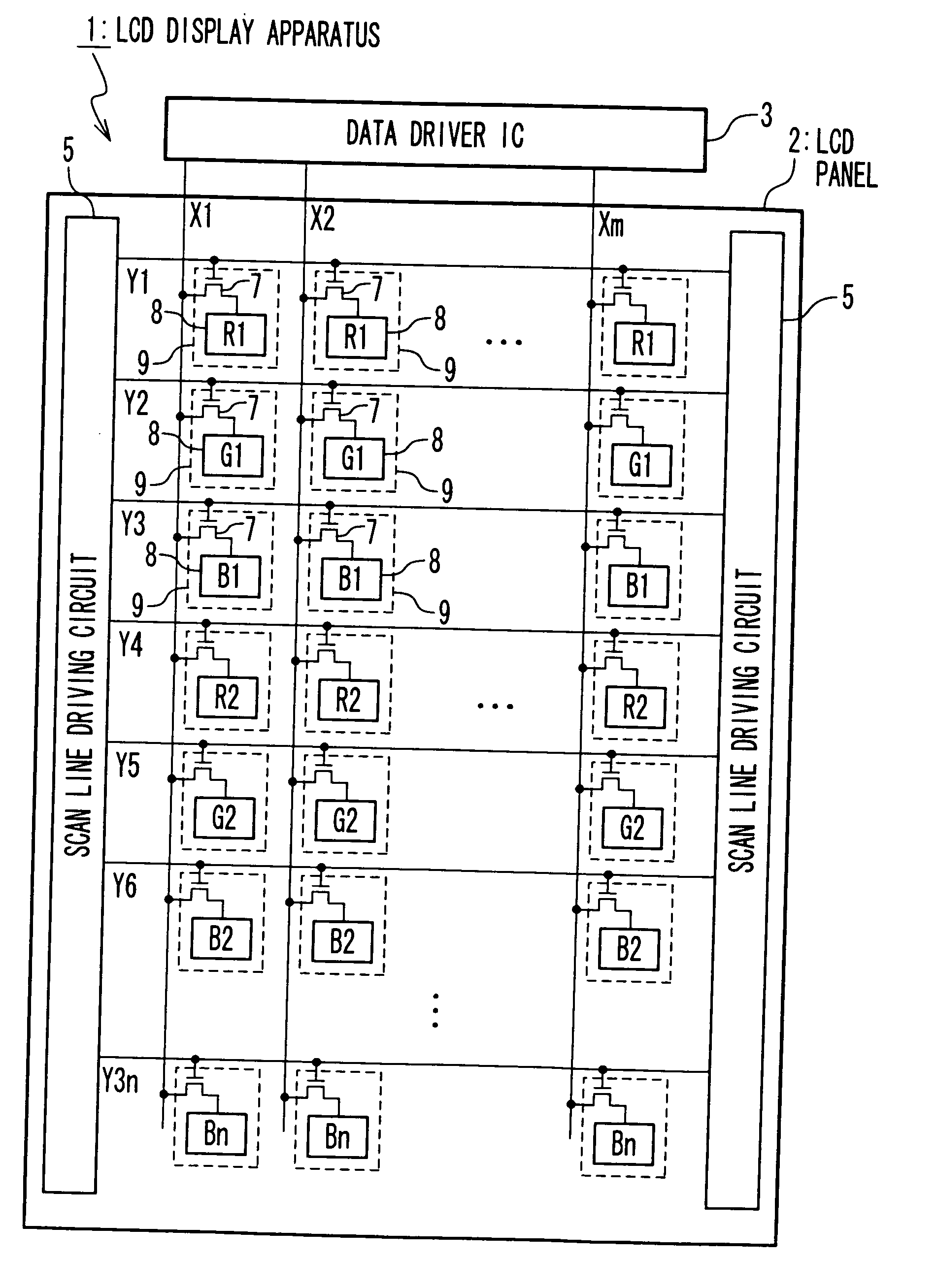
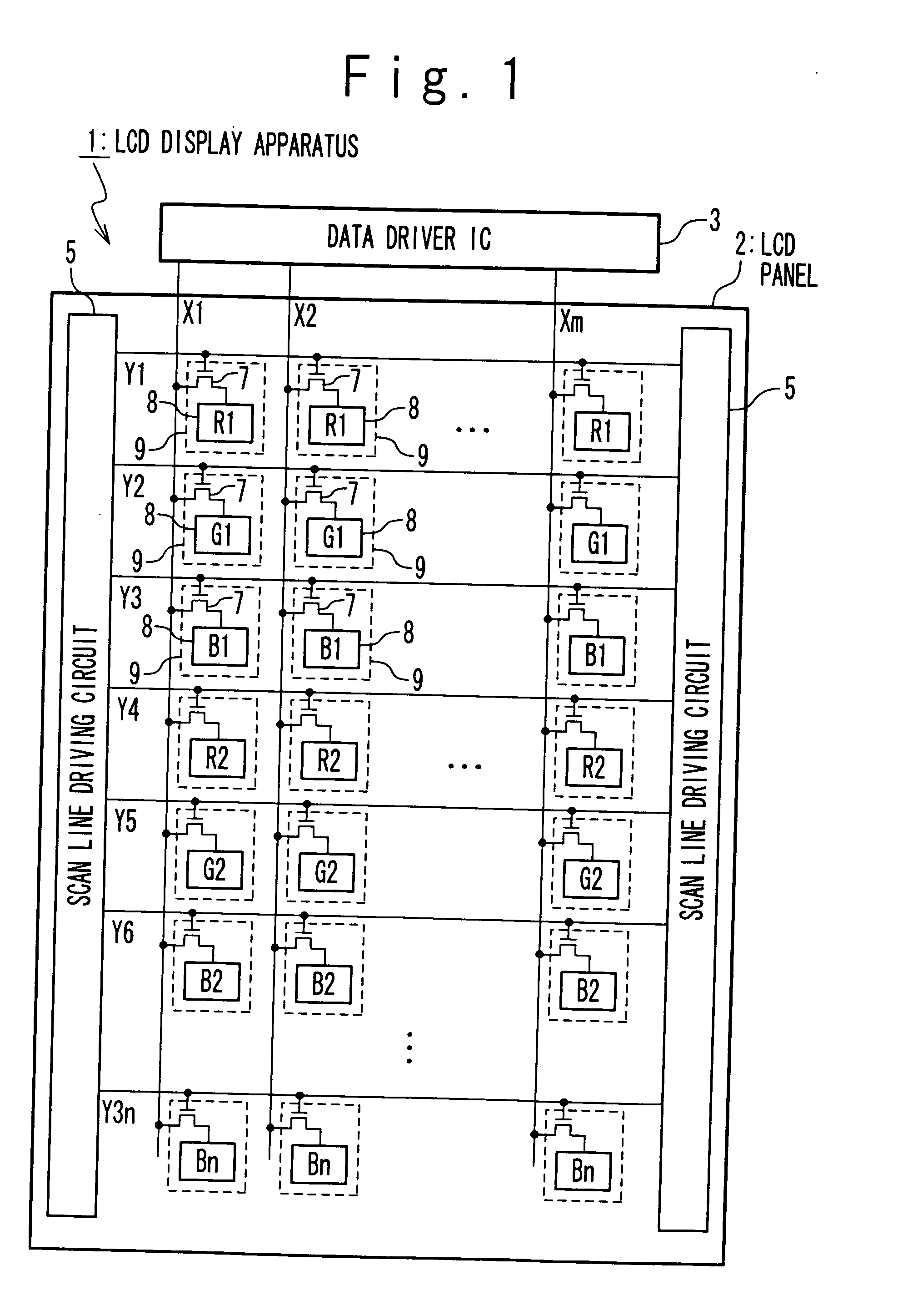
[0035]FIG. 1 is a block diagram showing a configuration of a liquid crystal display apparatus according to a first embodiment of the present invention. The liquid crystal display apparatus 1 has a liquid crystal display panel 2 and a data driver IC 3 with a timing control circuit built therein. The data driver IC 3 drives data lines X1 to Xm of the liquid crystal display panel 2. Also, the data driver IC 3 supplies a control signal to a scan line driving circuit 5 and supplies a fixed voltage to a common electrode. As mounting states of the data driver IC 3, there are COG (Chip On Glass), COF (Chip On Film), TCP (Tape Carrier Package), etc.

[0036]In the liquid crystal display panel 2, the data lines X1 to Xm and scan lines Y1 to Y3n are formed, and liquid crystal cells 9 are formed at intersections of these lines to function as a display cell. The liquid crystal cell 9 is provided with a TFT 7 (Thin Film Transistor) of functioning as a switching element and a pixel electrode 8. A liq...

second embodiment

[0097]In a second embodiment, although it is the same as the first embodiment that a scan line corresponding to green (G) is first selected in the each scan group immediately after the precharge, the scan order of a scan line corresponding to red (R) and a scan line corresponding to blue (B) is changed every two frame periods. The selection order of the scan lines corresponding to red (R) and the scan line corresponding to blue (B) may be changed every two horizontal periods and every two frame periods.

[0098]FIG. 7 is a conceptual diagram showing a method for driving the liquid crystal cell 9 in the second embodiment. In a (4j−3)th frame period and a next (4j−2)th frame period, the scan lines of the each scan group are driven in an order of the scan line corresponding to green (G), the scan line corresponding to red (R), and the scan line corresponding to blue (B). More specifically, a scan sequence of the scan lines Y1 to Y3n is an order of the scan lines Y2, Y1, Y3, Y5, Y4, Y6, . ...

third embodiment

[0104]In a third embodiment, it is prevented that by preliminarily scan the scan lines of green (G), red (R), and blue (B) and making their scan periods overlap one another, the driving periods of the pixel electrodes 8 in the liquid crystal cells 9 of red (R) and blue (B) become short. More specifically, as shown in FIG. 8, a scan period (a period from the time t11 to the time t13) of the scan line Y2 corresponding to green (G) and a scan period (a period from the time t12 to the time t16) of the scan line Y1 corresponding to red (R) overlap in the period from the time t12 to the time t13. Similarly, a scan period (a period from the time t12 to the time t16) of the scan line Y1 corresponding to red (R) and a scan period (a period from the time t15 to the time t18) of the scan line Y3 corresponding to blue (B) overlap in the period from the time t15 to the time t16.

[0105]In the first embodiment described above, the driving period TG (a period from the time t11 to the time t14) of th...


PUM


Abstract

A method of driving a display panel is provided. The display panel includes a first scan group including first to third scan lines, and a plurality of data lines which intersect the first to third scan lines, and first display cells of a first color which are connected with the first scan line, second display cells of a second color which are connected with the second scan line, third display cells of a third color which are connected with the third scan line. The method is achieved by precharging the data lines to a predetermined voltage in a first horizontal period; and by supplying a data signal to the first to third display cells through the data lines driving of the first to third display cells after the data lines are precharged in the first horizontal period. In the driving of the first to third display cells, one of the first to third display cells corresponding to one of said first to third colors, having a maximum spectral luminous efficacy, is first driven.

Description

INCORPORATION BY REFERENCE [0001]This patent application claims priorities on convention based on Japanese Patent Application Nos. 2008-170543 and 2009-145561. The disclosures thereof are incorporated herein by reference.BACKGROUND OF THE INVENTION [0002]1. Field of the Invention[0003]The present invention relates to a method for driving a display panel, and a display apparatus, and more specifically, to a technique of driving a display panel in which a color array of display cells is in a horizontal stripe pattern.[0004]2. Description of Related Art[0005]A liquid crystal display panel of a matrix type in which liquid crystal cells are arranged in a matrix is one of the most typical display apparatuses. The liquid crystal display panel is provided with the liquid crystal cells, scan lines, each of which selects a row of the liquid crystal cells, and data lines through which the data signal is supplied. The liquid crystal cells are arranged at intersection positions of the scan lines...

Claims


Application Information

Patent Timeline
IPC IPC(8): G09G5/10G09G3/36
CPCG09G3/2003G09G3/3225G09G2310/0248G09G3/3648G09G2310/0213G09G3/3614
Inventor HASHIMOTO, YOSHIHARUOOTANI, KEIGO
Owner RENESAS ELECTRONICS CORP
Why Eureka
Try Eureka