
Marine seismic acquisition with controlled streamer flaring

a streamer flaring and seismic data technology, applied in seismology, seismology, instruments, etc., can solve the problems of affecting the quality and utility of the resulting seismic data, the relative position of marine seismic receivers is variable, and the gap in the acquired seismic data is reduced or eliminated.

Active Publication Date: 2010-01-07
CONOCOPHILLIPS CO
View PDF14 Cites 42 Cited by
  • Summary
  • Abstract
  • Description
  • Claims
  • Application Information

AI Technical Summary

Benefits of technology

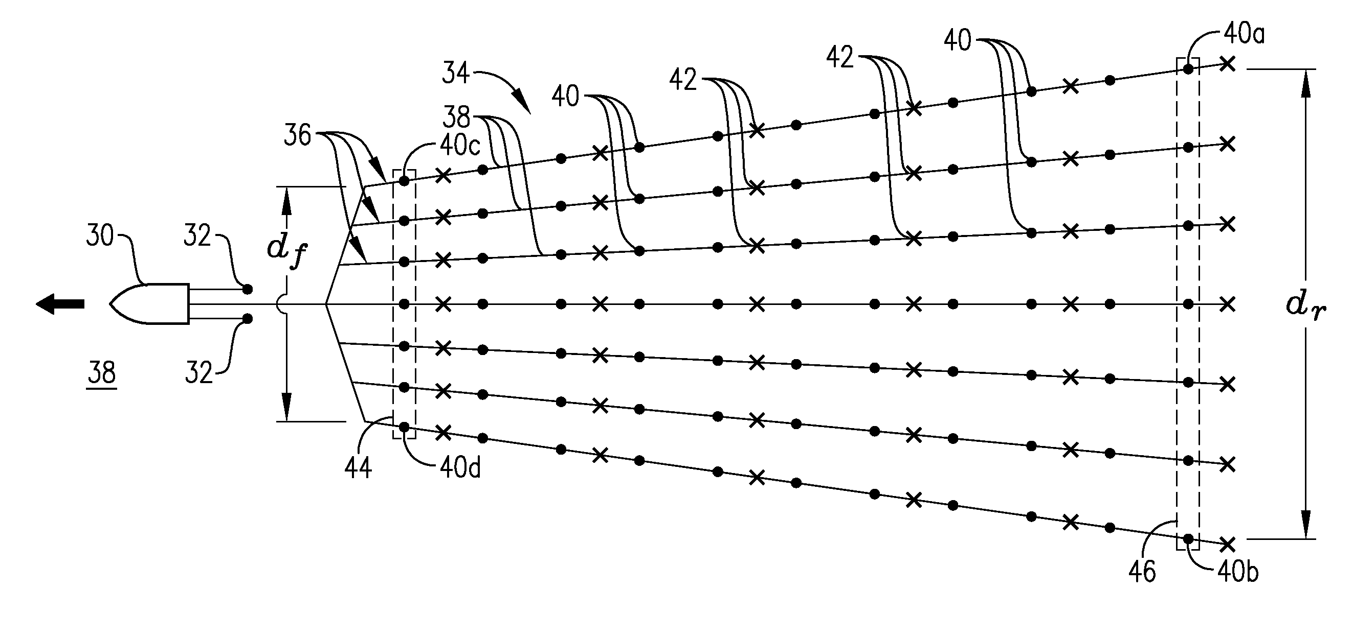
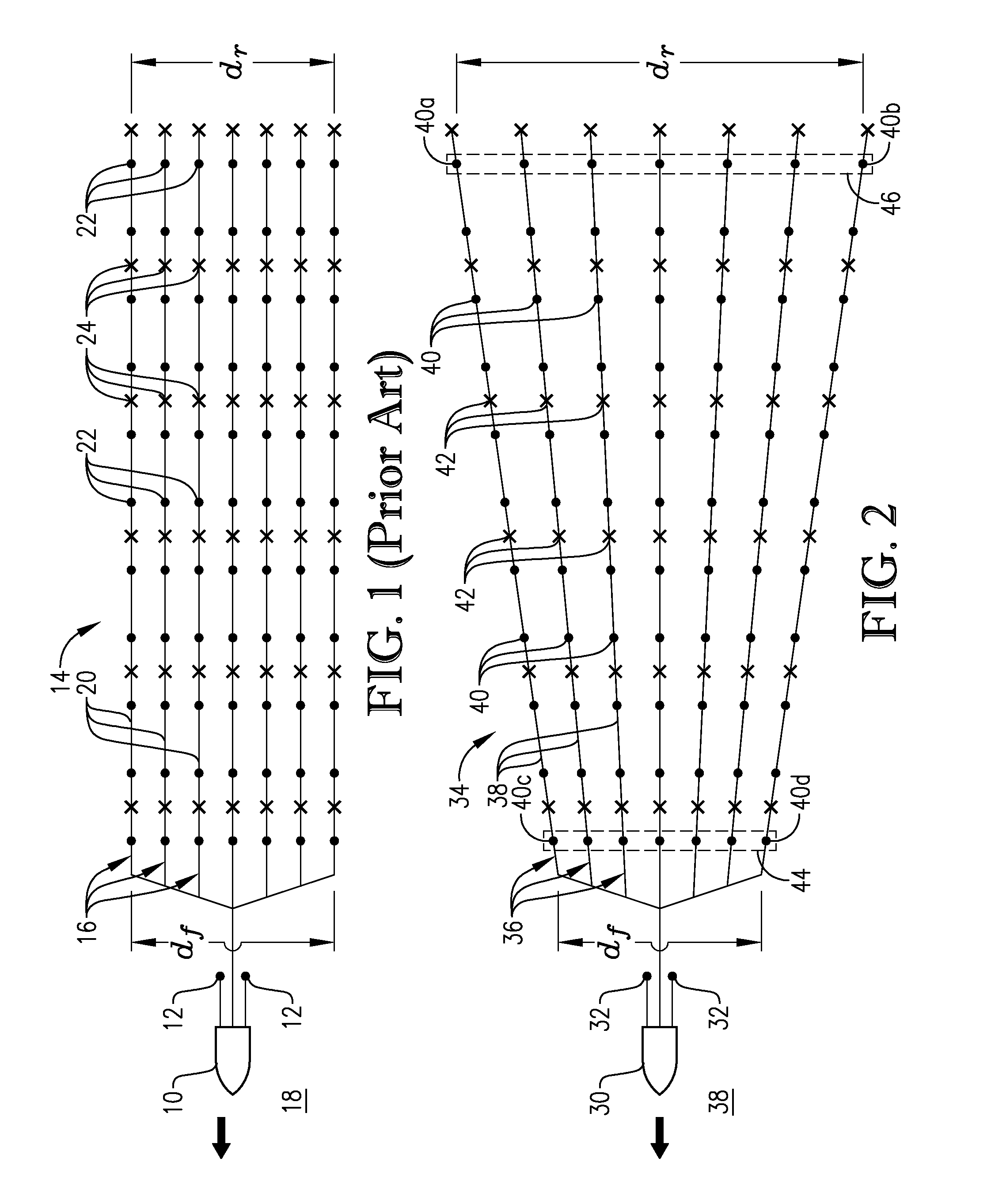
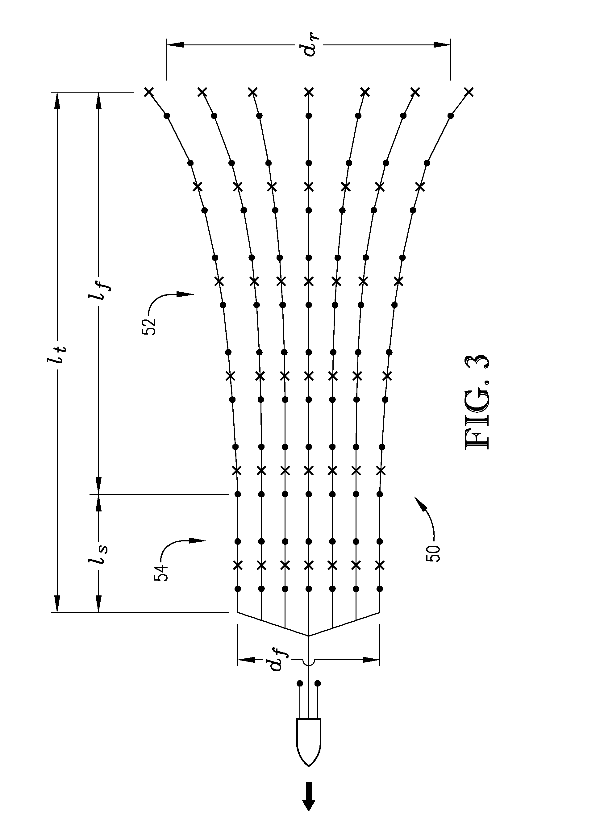
[0010]Although the prior art teaches that streamer flaring during seismic data acquisition should be avoided, the inventors have discovered that the use of controlled streamer flaring can reduce or eliminate the need for in-filling, without requiring more equipment or more acquisition passes than conventional marine seismic surveying techniques.

Problems solved by technology

It is known that the relative positions of the marine seismic receivers during seismic data acquisition can affect the quality and utility of the resulting seismic data.
However, unpredictable environmental forces such as currents, winds, and sea states present in many marine environments can cause the relative positions of marine seismic receivers to vary greatly as they are towed through the water.
A common problem encountered with conventional marine seismic surveys is “gaps” in the acquired seismic data.
These data gaps can occur when the spacing between adjacent acquisition passes is too large to provide sufficient resolution for proper data processing.
Even when steerable streamers are employed, gaps in seismic data are common, particularly when strong crosscurrents are present.
When strong crosscurrents are present during seismic data acquisition, it is not practical to maintain all the streamers in an orientation that is parallel to the direction of travel of the towing vessel because fighting strong crosscurrents with steering devices produces noise that dramatically reduces the quality of the gathered seismic data.
When gaps in marine seismic data are discovered, the areas corresponding to the data gaps must be resurveyed—a process commonly known as “shooting in-fill” or “in-filling.” Unfortunately, the existence of gaps in marine seismic data may not be discovered until the initial marine seismic survey has been completed and the resulting seismic data is being processed.
Obviously, in-filling is very undesirable because of the significant expense and time involved in resurveying in-fill areas that may be located hundreds of kilometers from one another or even retransiting the same vessel pass again to make up coverage.

Method used


Image

  • Marine seismic acquisition with controlled streamer flaring
  • Marine seismic acquisition with controlled streamer flaring
  • Marine seismic acquisition with controlled streamer flaring

Examples


Embodiment Construction

[0015]Referring initially to FIG. 2, a marine seismic data acquisition system according to one embodiment of the present invention is illustrated as generally comprising a marine vessel 30, marine seismic sources 32, and a marine seismic streamer system 34. The marine seismic streamer system 34 of FIG. 2 is depicted in a flared configuration. In accordance with various embodiments of the inventive marine seismic data acquisition process described herein, the streamer system 34 is intentionally maintained in a flare configuration and is used to gather marine seismic data, while the marine vessel 30 tows the seismic sources 32 and the streamer system 34 through a body of water 38.

[0016]The marine vessel 30 can be any vessel capable of towing the seismic sources 32 and the seismic streamer system 34 through the body of water 38 at an appropriate speed. Generally, appropriate speeds for the marine seismic data acquisition methods of the present invention can be in the range of 2 to 10 k...


PUM


Abstract

Marine seismic data is acquired with a system of steerable seismic streamers that are intentionally maintained in a flared configuration while the streamers are towed through a body of water.

Description

BACKGROUND[0001]1. Field of the Invention[0002]The present invention relates to seismic data acquisition. More particularly, the invention relates to the acquisition of seismic data in marine environments.[0003]2. Brief Description of the Prior Art[0004]Marine seismic exploration investigates and maps the structure and character of subsurface geological formations underlying a body of water. Marine seismic data is typically gathered by towing seismic sources (e.g., air guns) and seismic receivers (e.g., hydrophones) through a body of water behind one or more marine vessels. As the seismic sources and receivers are towed through the water, the seismic sources generate acoustic pulses that travel through the water and into the earth, where they are reflected and / or refracted by interfaces between subsurface geological formations. The seismic receivers sense the resulting reflected and / or refracted energy, thereby acquiring seismic data that provides information about the geological fo...

Claims


Application Information

Patent Timeline
Patent Type & Authority Applications(United States)
IPC IPC(8): G01V1/38
CPCG01V1/38G01V1/3817
Inventor BREWER, JOEL D.EICK, PETER M.
Owner CONOCOPHILLIPS CO
Learn More