Optical Isolator

a technology of optical isolators and polarizers, applied in the direction of optical waveguide light guides, instruments, polarising elements, etc., can solve the problems of difficult chip integration, large optical isolator types, and large construction costs of faraday rotators and polarizers

Active Publication Date: 2010-01-07
DUKE UNIV
View PDF0 Cites 11 Cited by
  • Summary
  • Abstract
  • Description
  • Claims
  • Application Information

AI Technical Summary

Benefits of technology

[0005]A particular embodiment is constructed as a single-mode waveguide on a substrate. The cross-section of the waveguide is inhomogeneous in terms of materials. At least one part of the cross-section is a non-reciprocal magneto-optic medium, which has nonzero off-diagonal permittivity tensor components. This inhomogeneity induces the propagation constant shift,

Problems solved by technology

Thus, this type of optical isolator becomes relatively large.
It is also a challenge to build Faraday rotators and polarizers in a

Method used


Image

  • Optical Isolator
  • Optical Isolator
  • Optical Isolator

Examples


Embodiment Construction

[0017]The following description is presented to enable any person skilled in the art to make and use the invention, and is provided in the context of particular applications and their requirements. Various modifications to the exemplary embodiments will be readily apparent to those skilled in the art, and the generic principles defined herein may be applied to other embodiments and applications without departing from the spirit and scope of the invention. Thus, the present invention is not intended to be limited to the embodiments shown, but is to be accorded the widest scope consistent with the principles and features disclosed herein.

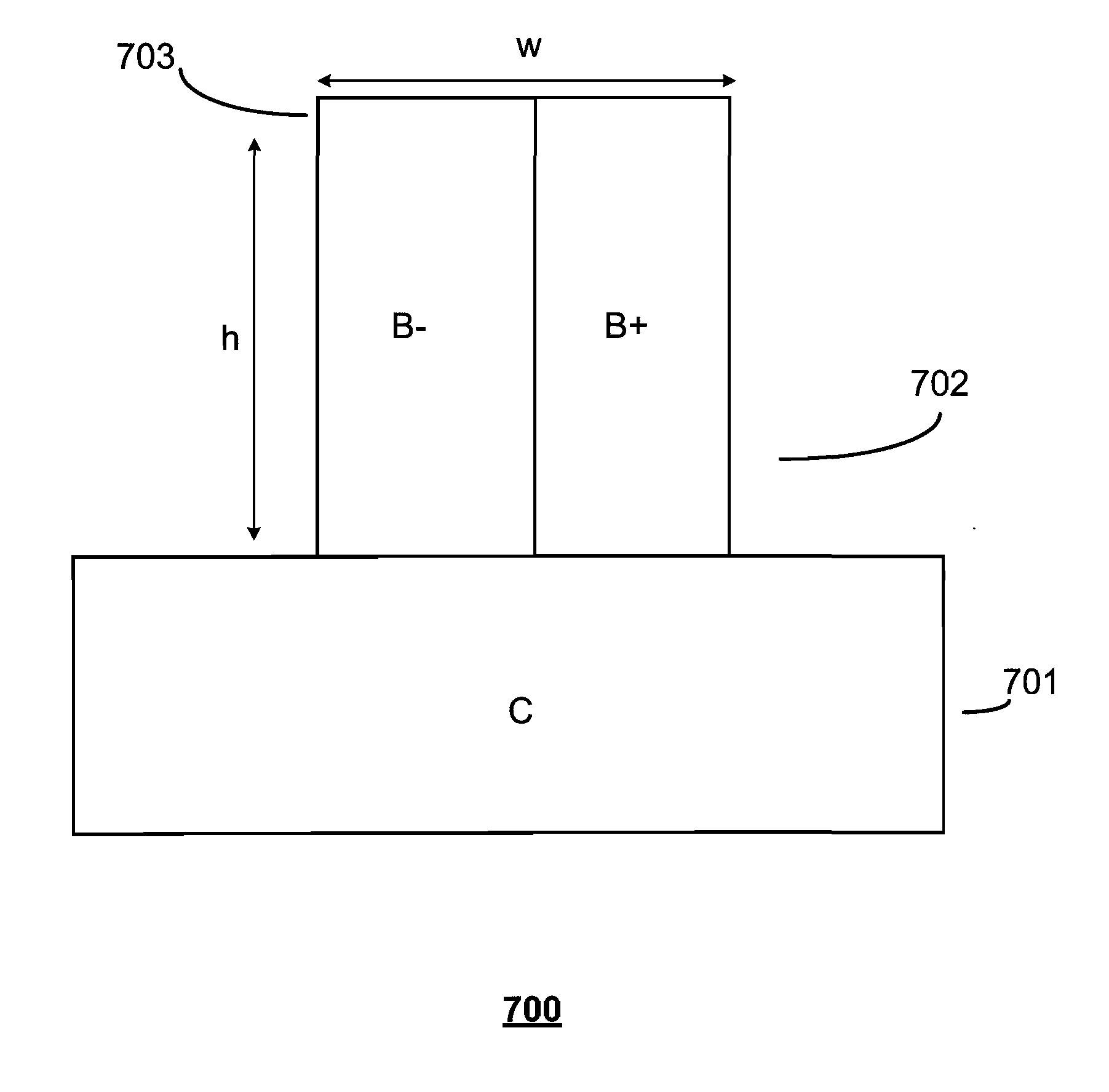
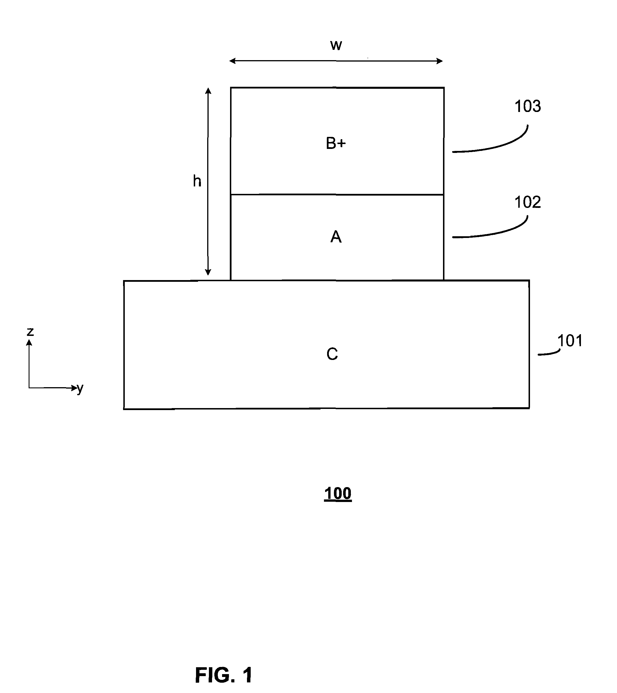
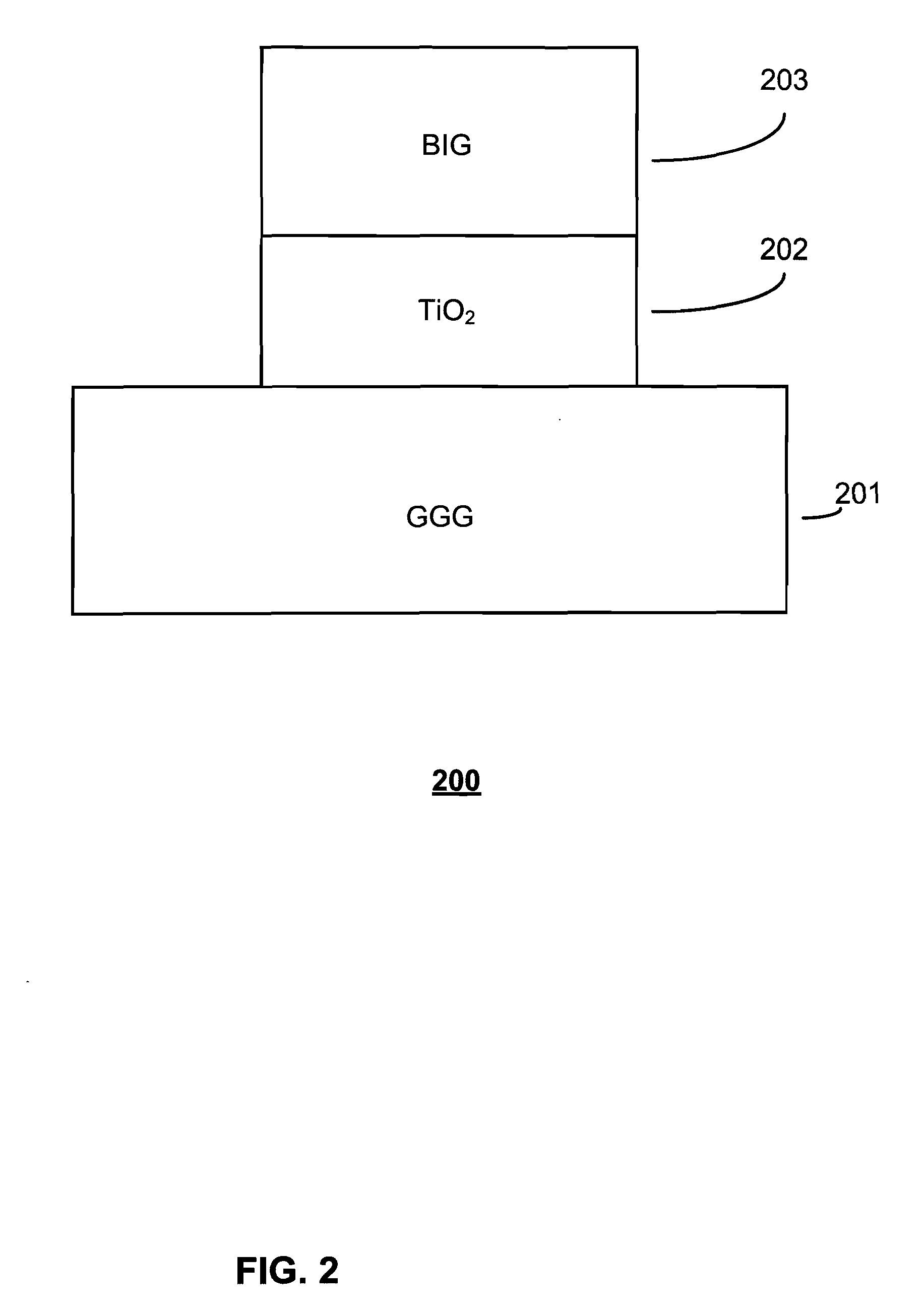
[0018]FIG. 1 illustrates an optical isolator 100 in accordance with one embodiment of the invention. Optical isolator 100 includes substrate portion 101, first waveguide portion 102, and second waveguide portion 103. Substrate portion 101 comprises a low index material C. In one embodiment, material C has a permittivity of 2.13ε0 where ε0 is the permi...


PUM


Abstract

Various optical isolator embodiments are disclosed. Embodiments comprise a waveguide section utilizing materials that induce a propagation constant shift that is propagation-direction-dependent. Embodiments are characterized by a cutoff frequency for forward propagating waves that is different than the cutoff frequency for reverse waves; the dimensions and direction of magnetization of the waveguide can be tailored so that, in a particular embodiment, the cutoff frequency for forward propagating waves is lower than the cutoff frequency for reverse waves. A particular embodiment is constructed as a single-mode waveguide on a substrate. The cross-section of the waveguide is inhomogeneous in terms of materials. At least one part of the cross-section is a non-reciprocal magneto-optic medium, which has nonzero off-diagonal permittivity tensor components. This inhomogeneity induces a propagation constant shift, which is propagation-direction-dependent. This device works as an optical isolator from the cut-off frequency of the lowest forward wave (lower frequency) to one for the lowest reverse wave (higher frequency). Various configurations consistent with the principles of the invention are disclosed.

Description

CROSS REFERENCE TO RELATED APPLICATION[0001]This application claims the benefit of U.S. Provisional Application No. 61 / 133,609 filed Jul. 1, 2008.BACKGROUND OF THE INVENTION[0002]Optical isolators are optical components that transmit light in one direction but block it in the backward-propagating direction. They are used when the reversely-propagating light needs to be avoided. For example, lasers become instable when reflected light comes back to them.[0003]Conventional optical isolators consist of a Faraday rotator and two polarizers. The linear-polarization angle needs to be rotated by 45 degrees in a Faraday rotator, which is typically a few millimeters long. Thus, this type of optical isolator becomes relatively large. It is also a challenge to build Faraday rotators and polarizers in a guided-optics format, i.e. it is hard to integrate them on chip. In order to construct guided-wave optical isolators, an asymmetric Mach-Zehnder waveguide interferometer is commonly used. This o...

Claims


Application Information

Patent Timeline
IPC IPC(8): G02B6/12G02B6/00G02B27/28
CPCG02B6/122G02B2006/12097G02B2006/12035G02B6/2746
Inventor YOSHIE, TOMOYUKITANG, LINGLINGDREZDZON, SAMUEL
Owner DUKE UNIV
Why Eureka
Try Eureka