

Apparatus and Method for Assembling Structural Components
- Summary
- Abstract
- Description
- Claims
- Application Information
AI Technical Summary
Benefits of technology
Problems solved by technology
Method used
Image

Examples
Embodiment Construction
[0021]With reference to the figures in which like numerals represent like elements throughout, embodiments of the present invention are shown. The figures and the following description are for a limited number of embodiments for ease of understanding. However, the invention is not limited to these illustrative embodiments.
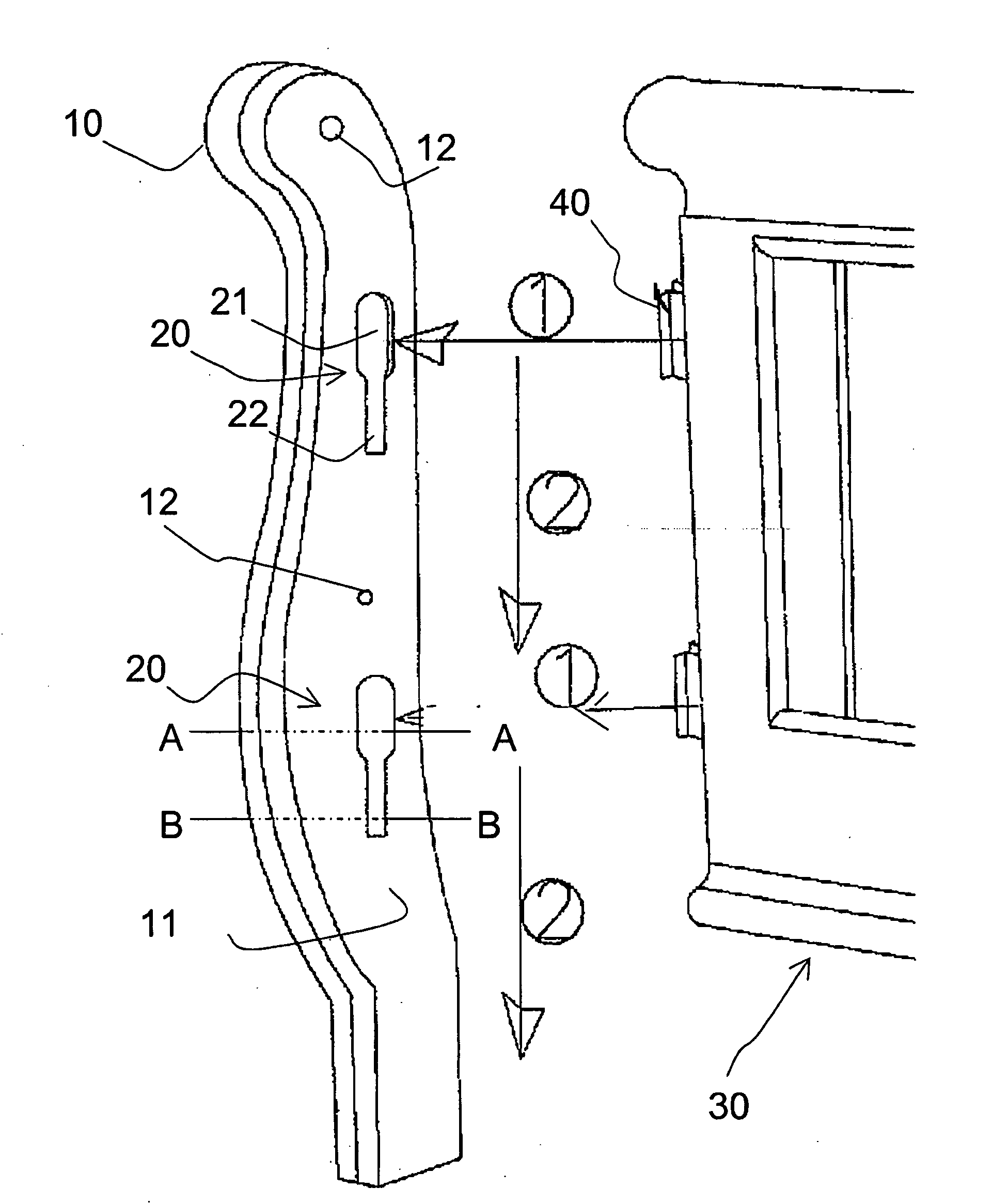
[0022]In reference to FIG. 1, structural members to be joined in accordance with the present invention are shown in their respective alignments for joining. For purposes of illustration the embodiment of the present invention shown is that of a headboard for a bed frame. However, as will be appreciated, the invention is suited to a wide range of applications, such as for furniture, cabinetry, any other use where it may find utility in joining structural members. A first structural member 10 is shown, which in this instance is a vertical post of a headboard, having a first mating surface 11. At least one keyed slot 20 is defined in the first mating surface 11 of the...
PUM
 Abstract
Description
Claims
Application Information