Withdrawing mechanism

a technology of swinging mechanism and swinging speed, which is applied in the direction of shock absorbers, wing accessories, manufacturing tools, etc., can solve the problems of increasing the resistance of the swinging operation of the door toward the closed position, the device cannot withdraw the door, and the impact is difficult to be properly absorbed, so as to achieve the effect of preventing a large force, reducing the swinging speed of the swinging member, and reducing the resistance to the swinging operation of the door toward th

Inactive Publication Date: 2010-01-14
NIFCO INC
View PDF3 Cites 10 Cited by
  • Summary
  • Abstract
  • Description
  • Claims
  • Application Information

AI Technical Summary

Benefits of technology

[0077]In accordance with the withdrawing mechanism of the present invention, it is possible, as a first advantage, to act in response to the swinging speed of the swingable member toward the reference position so that when the kinetic energy is large, a larger damping force is applied to the swinging operation of the swingable member while when the kinetic energy is small, a smaller damping force is accordingly applied to the swinging operation of the swingable member, with the result that when the swinging operation of the swingable member is hard, the swinging operation is effectively damped while when the swingable member is normally swung from an open position toward the reference position, the resistance to the swinging operation is prevented from being excessive at a certain swung position and thereafter. In other words, it is possible to effectively damp the swinging speed of the swingable member toward the reference position if the swingable member is swung hard in an unusual way, while it is possible to prevent a large force from being applied to the swinging operation of the swingable member toward the reference position in a normal situation.
[0078]It is possible, as a second advantage, to swing the swingable member to the reference position to cause the catcher to properly capture the striker in order to return the catcher to a desired position even if the striker disposed on the swingable member for capturing the striker by the catcher is improperly set in the turned position with the swingable member being opened.
[0079]It is possible, as a third advantage, to cause the catcher to capture the striker and to withdraw the swingable member, applying a damping force to the swingable member in such a state wherein the swingable member has been swung toward the reference position to some extent.
[0080]It is possible, as a fourth advantage, to dispose the catcher and the damper without excessively extending the length in the depth direction.

Problems solved by technology

However, the device disclosed in Patent Document 1 has a first problem in that it is in such a dilemma that if an attempt is made to increase the damping force of a damper for damping a swinging operation in order to absorb impact caused during swinging the door toward the closed position, the resistance to the swinging operation of the door toward the closed position increases while if an attempt is made to decrease the resistance, it is difficult to properly absorb the impact caused when the door is swung hard.
The device has a second problem in that in a case where the turnable plate has been turned into the turned position for some reason with the door opened, even if the door is closed, the retractable pin is prevented from entering the spiral slot of the turnable plate set in the turned position, which leads to operation wherein the turnable plate is required to be returned to the standby position.
The device has a third problem in that since the retractable pin is disposed on a free end of the door, the device cannot withdraw the door until just before the door is about to be closed.
The device has a fourth problem in that the turnable plate and the damper for damping a swinging operation need to have a certain depth for installation since the damping force is generated by bringing a gear disposed in the damper into direct engagement with a sector gear formed on the turnable plate.

Method used


Image

  • Withdrawing mechanism
  • Withdrawing mechanism
  • Withdrawing mechanism

Examples


Embodiment Construction

[0106]Now, the best modes for carrying out the invention will be described based on FIG. 1 to FIG. 25.

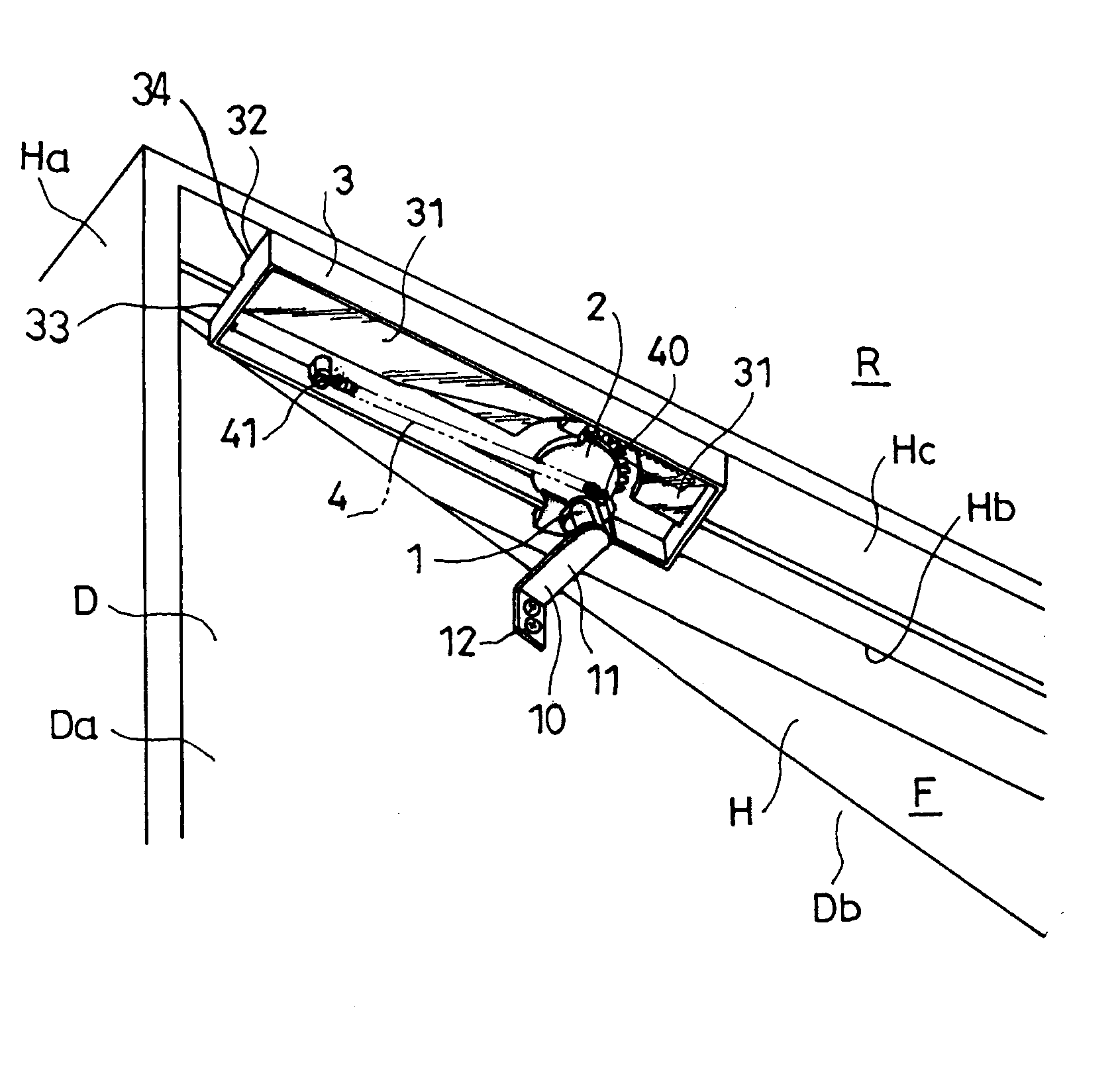
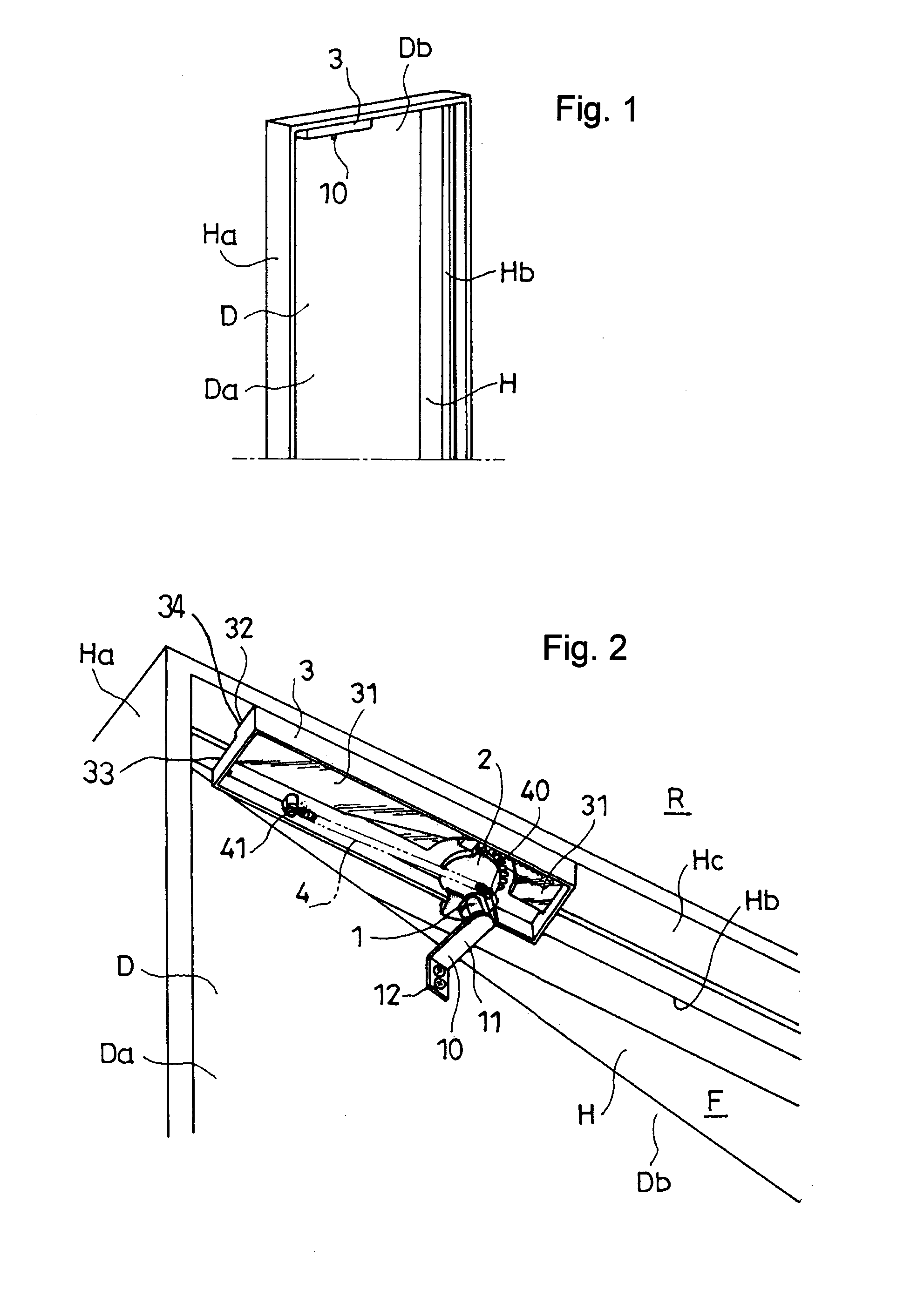
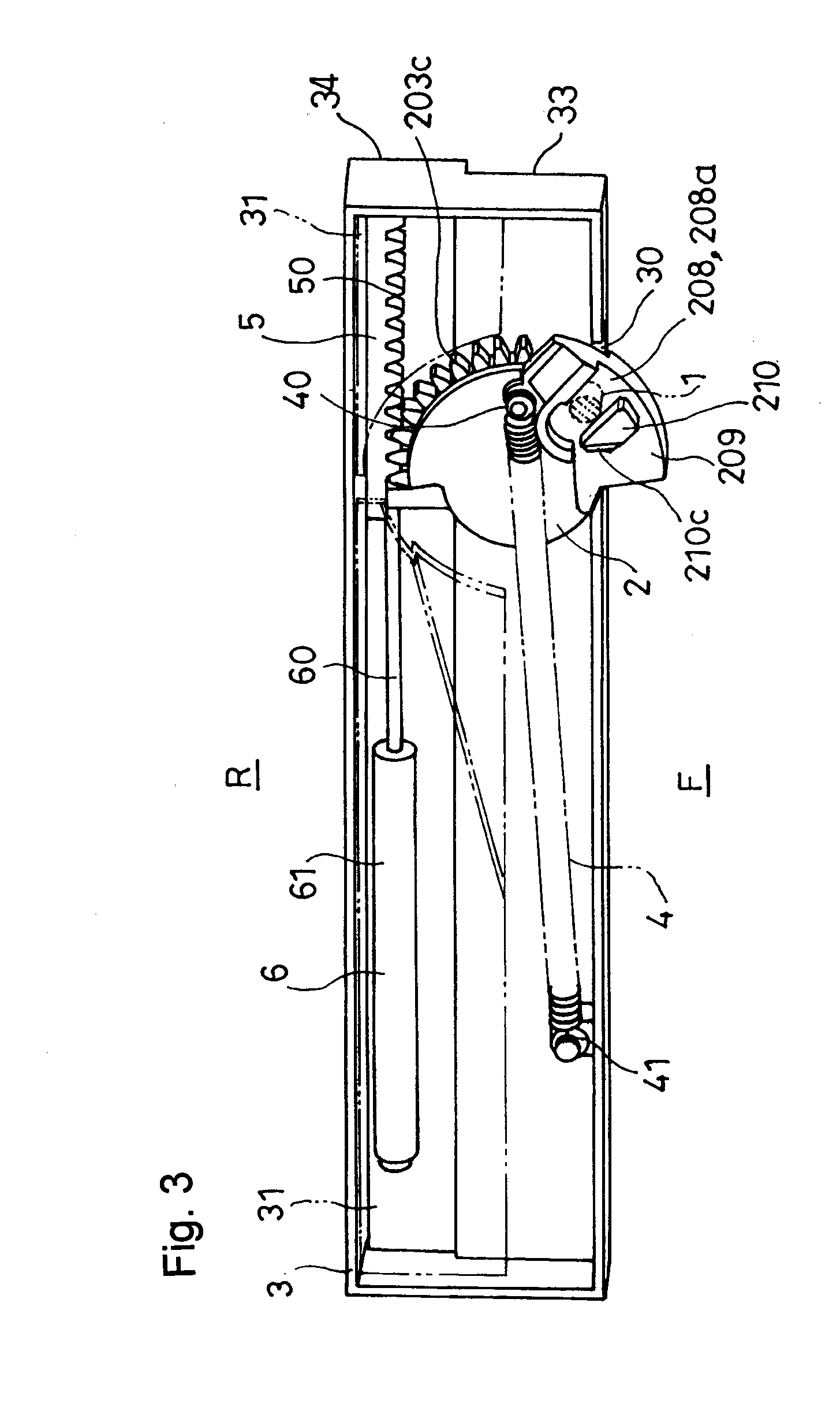
[0107]FIG. 1 to FIG. 3 show a state wherein a catcher 2 forming the withdrawing mechanism according to the present invention is set in a standby position and wherein a swingable member D has been swung in a certain swung position with the catcher 2 capturing a striker 1. FIG. 1 shows an upper portion Db of the swingable member D, FIG. 2 shows the upper portion Db in an enlarged view, and FIG. 3 shows essential parts of the withdrawing mechanism in this state.

[0108]FIG. 4 to FIG. 6 show a state wherein the catcher 2 forming the withdrawing mechanism according to the present invention is set in a turned position, and wherein the catcher 2 in this position has captured the striker 1 to set the swingable member D in a reference position. FIG. 4 shows the upper portion Db of the swingable member D, FIG. 5 shows the upper portion Db in an enlarged view, and FIG. 6 shows essential parts of...


PUM


Abstract

A withdrawing mechanism includes a striker disposed on one of a swingable member and a main body, a catcher disposed on the other of the swingable member and the main body, and a damper for applying a damping force to a turning operation of the catcher toward a turned position. The catcher includes a casing, a rotational plate having a hooking groove for catching the striker therein, and a spring attached between an attaching portion of the rotational plate and a fixing portion of the casing to pull and rotate the rotational plate.When the rotation plate catches the striker, the rotational plate rotates in a direction to pull the spring, and when the attaching portion passes a position on a linear line extending the attaching portion, rotational center of the rotational plate and fixing portion, the rotational plate is pulled to move the rotational plate to the turned position.

Description

CROSS-REFERENCE TO RELATED APPLICATION[0001]This is a divisional application of Ser. No. 12 / 149,477 filed on May 2, 2008.TECHNICAL FIELD[0002]The present invention relates to an improved withdrawing mechanism for absorbing impact, which is caused when a swingable member is swung from an open position to a reference position as in, e.g. a case where a door is closed.BACKGROUND ART[0003]A conventional door-opening device, which includes a retractable pin disposed to a door and a turnable plate disposed on a housing, has been disclosed in Patent Document 1. The turnable plate has a spiral slot formed therein and is configured to be stably set in both of a position with the opening of the spiral slot directed to a front direction (standby position) and a position with the opening of the spiral slot directed to a depth direction (turned position) by a spring, which has one end fixed at a position away from the pivot thereof and the other end fixed to the housing. When the door is swung t...

Claims


Application Information

Patent Timeline
Patent Type & Authority Applications(United States)
IPC IPC(8): E05F5/02E05F5/06E05C3/12E05F1/14E05F3/10
CPCE05F3/102E05F5/027E05Y2900/132E05F3/227Y10T16/299Y10T16/56Y10T16/276Y10T16/27Y10T16/293Y10T16/625Y10T16/61Y10T16/2804Y10T16/62Y10T292/1043F16F9/32B62D25/12F16F9/19E05B77/38
Inventor TOMIOKA, KAZUYUKITOMIJI, KATSUYASU
Owner NIFCO INC
Why Eureka
Try Eureka