Combustion liner for a gas turbine engine

Active Publication Date: 2010-01-14
MECHANICAL DYNAMICS & ANALYSIS
View PDF33 Cites 18 Cited by
  • Summary
  • Abstract
  • Description
  • Claims
  • Application Information

AI Technical Summary

Benefits of technology

[0007]The use of columns increases the heat transfer coefficient while

Problems solved by technology

The combustion liner becomes quite hot during operation.
This de

Method used


Image

  • Combustion liner for a gas turbine engine
  • Combustion liner for a gas turbine engine
  • Combustion liner for a gas turbine engine

Examples


Embodiment Construction

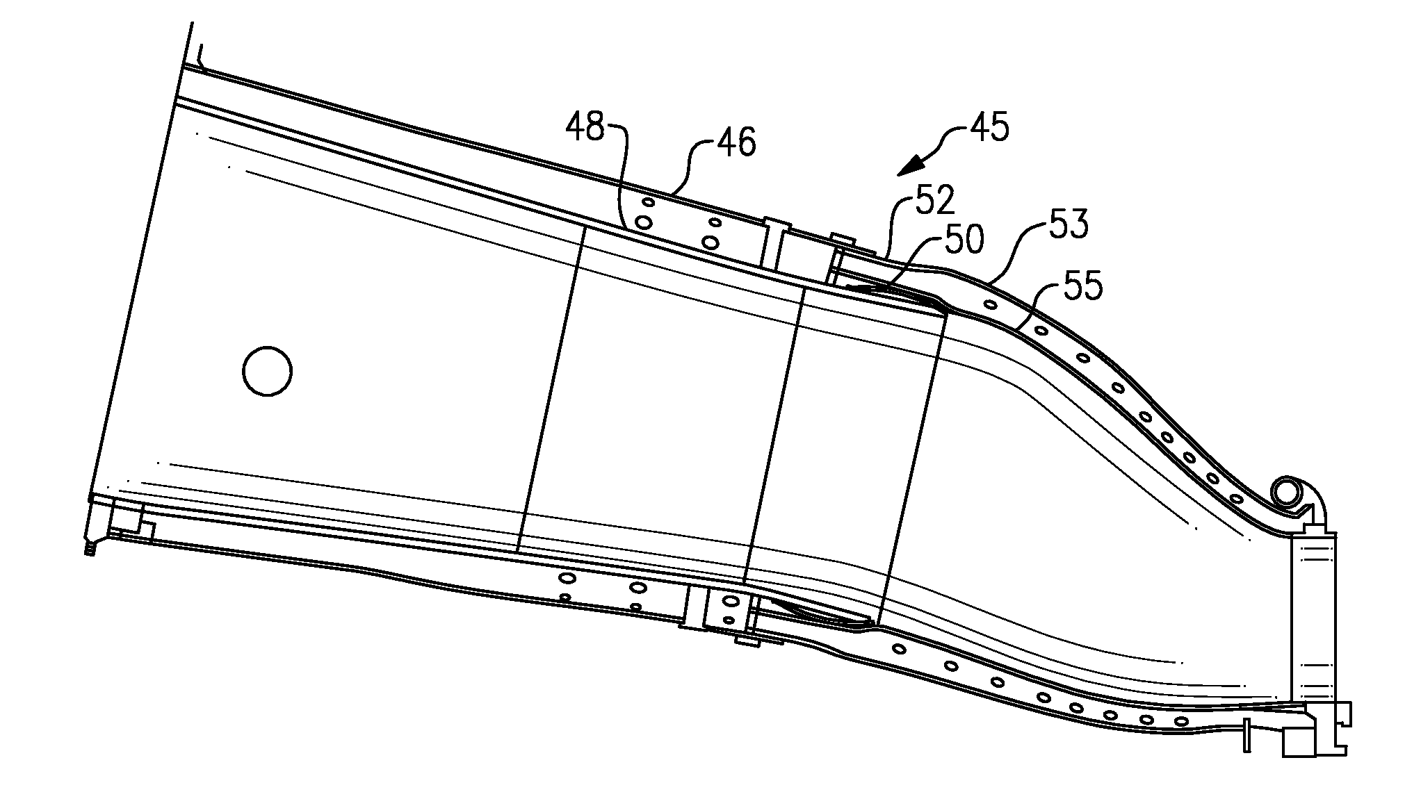
[0014]FIG. 1 shows a combustion duct assembly 45 for communicating an upstream combustion section to a downstream turbine section. An outer housing 46 sits outwardly of a transition duct 52. A combustion liner 48, which includes a component known as a flow sleeve, and which is shown somewhat schematically in this view, also includes a hula seal 50 attached to a liner body. The hula seal 50 is forced into an inner wall 55 of the transition duct 52, which is spaced from an outer wall 53. The outer housing 46 is sealed on the outer wall 53.

[0015]The hula seal 50 is biased against the inner wall 55, and thus serves to hold the combustion liner 48 to the transition duct 52. However, the two can slide relative to each other when there is relative expansion due to the hot gasses that will flow within the combustion liner 48.

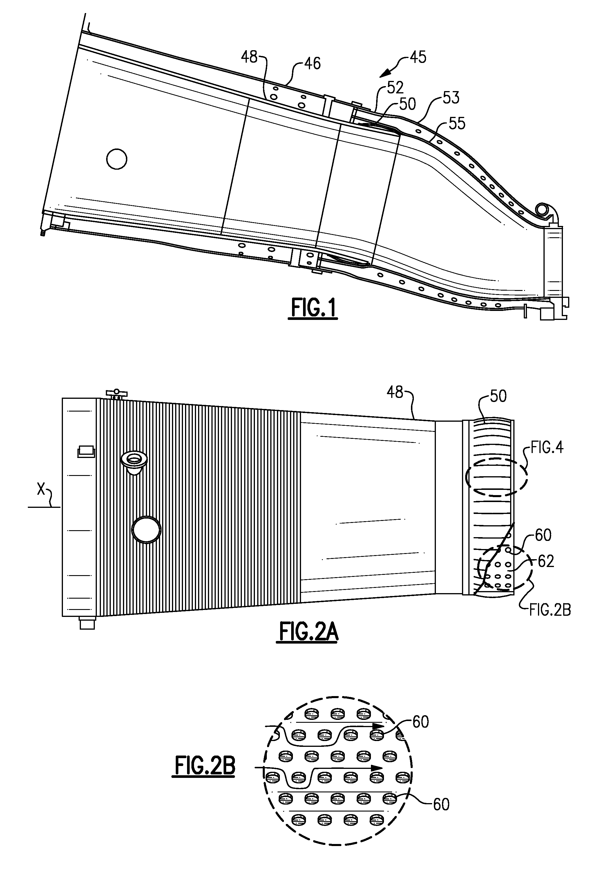
[0016]FIG. 2A shows the combustion liner 48, and its attached hula seal 50. An axis X extends axially from an upstream end (to the left of FIG. 2A) toward a downstream ...


PUM


Abstract

A combustion duct assembly has a transition duct and a combustion liner having a hula seal at a downstream end that is forced within an inner wall of the transition duct. The combustion liner is held within the transition duct by the hula seal, but allowed to move relative to the transition duct. The combustion liner is formed with heat transfer columns adjacent the downstream end, and radially inwardly of the hula seal.

Description

BACKGROUND OF THE INVENTION[0001]This application relates to a combustion liner with cooling structure for a hula seal.[0002]Gas turbine engines are known, and include a compressor section compressing air and delivering it downstream to a combustion section. The compressed air is mixed with fuel in the combustion section and burned. Products of the combustion pass downstream to a turbine section.[0003]A combustion liner directs the products of combustion from the combustion section downstream to the turbine section. The combustion liner becomes quite hot during operation. As such, it is known to provide cooling air to cool the combustion liner.[0004]A downstream end of the combustion liner typically fits into a transition duct which is connected to the turbine section. A hula seal attached to the combustion liner provides a slidable connection to the transition duct. Since there can be a good deal of relative expansion between the transition duct and the combustion liner, the two co...

Claims


Application Information

Patent Timeline
IPC IPC(8): F02C1/00
CPCF01D9/023F23M5/085F05D2240/55F23R3/60F23R2900/00012F23R3/005
Inventor TU, JOHN S.SMITH, CRAIG F.CHOKSHI, JAISUKHLAL V.
Owner MECHANICAL DYNAMICS & ANALYSIS
Why Eureka
Try Eureka