
Detector assembly for detecting radiation with angular resolution and method for operating said assembly

a detector assembly and radiation detection technology, applied in the direction of optical radiation measurement, photometry using electric radiation detectors, instruments, etc., can solve the problems of less sensitivity of the detector, less probability of the respective detector responding, and more unfavorable transmission. , to achieve the effect of improving the data

Inactive Publication Date: 2010-01-14
GSI HELMHOLTZZENT FUR SCHWERIONENFORSCHUNG
View PDF7 Cites 38 Cited by
  • Summary
  • Abstract
  • Description
  • Claims
  • Application Information

AI Technical Summary

Benefits of technology

The detector assembly described in this patent provides a way to detect radiation with angular resolution using a detector element. The detector element has a front face and a rear face, and a space between them filled with continuous regions of detector material. The regions are arranged in a way that each region borders on the front and rear faces of the detector element. The detector material has predetermined physical properties that make it suitable for detecting specific types of radiation. The detector element interacts with the incident photons and produces signals that can be measured. The detector assembly can be used to detect high energy gamma radiation.

Problems solved by technology

In this case a low sensitivity of the detector is a drawback, in particular at high radiation energies, because only the gamma rays which are incident parallel to the axes of the holes or at a small aperture angle are to be used in the evaluation.
The higher the energy of the particles or radiation to be detected, the more unfavourable the transmission becomes and the lower the probability of the respective detector responding.
A drawback is that the scattering detector must be very thin so that at most one Compton interaction takes place therein.
This reduces the efficiency of the Compton camera.
However, no element-specific signal is detected in this way, explosive devices being detected only on the basis of their shape in the X-ray image.
This does not allow the detection of the direction of the gamma source, produced for example by neutron activation, relative to the detection system above the ground.
A further difficulty is the identification of individual emission lines, which are characteristic for example of nitrogen or other characteristic material or element compositions, from a measured intensity spectrum in order to detect the presence of explosives.
This involves a high technical expense and leads to lower reliability of the relevant detector.

Method used


Image

  • Detector assembly for detecting radiation with angular resolution and method for operating said assembly
  • Detector assembly for detecting radiation with angular resolution and method for operating said assembly
  • Detector assembly for detecting radiation with angular resolution and method for operating said assembly

Examples


Embodiment Construction

[0085]In the figures, like or functionally identical elements have been provided with the same reference numerals unless otherwise specified.

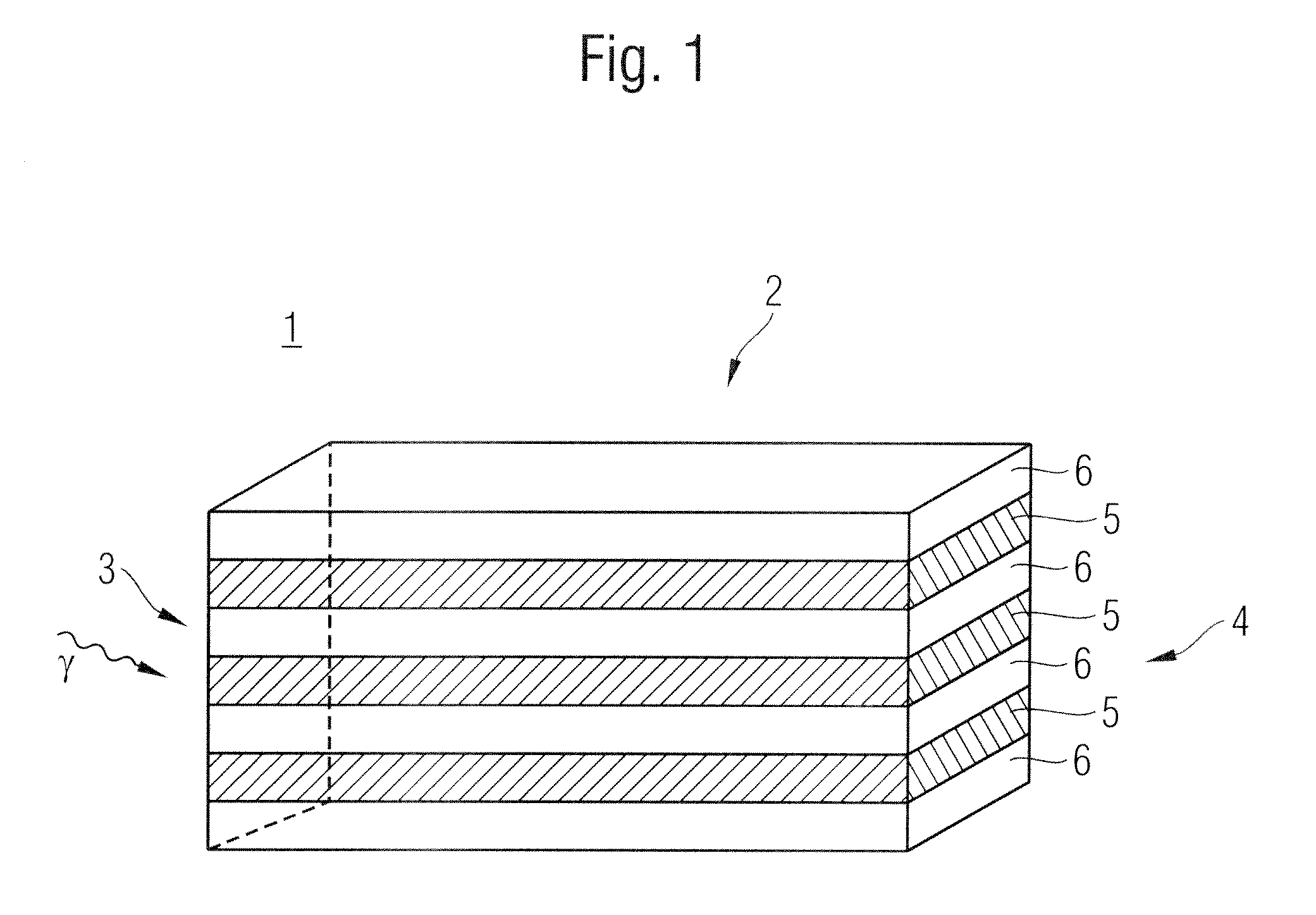
[0086]FIG. 1 shows a detector assembly 1 with a detector element 2 according to the invention. In the embodiment according to FIG. 1, the cuboid detector element 2 comprises a front face 3 and a rear face 4. In this case, gamma rays γ arrive in the detector element 2 substantially through the front face 3.

[0087]Alternating layers 5, 6 of a first detector material and a second detector material respectively are provided. These layers 5, 6 connect the front face 3 to the rear face 4. For example, the layers 5 are manufactured from an absorber material for Compton-scattered electrons and the layers 6 are manufactured from a scintillator material.

[0088]The light emission produced by the scintillator material is preferably measured at the rear face 4 of the detector element. From the amount of light measured, or the energy deposited in the layers 6 ...


PUM

PropertyMeasurementUnit
angleaaaaaaaaaa
thicknessesaaaaaaaaaa
energyaaaaaaaaaa

Abstract

A detector assembly for detecting radiation with angular resolution comprises at least one detector element, which comprises a front face and a rear face, a first detector material and a second detector material between the front face and the rear face, a space between the front face and the rear face of the detector element being filled by a plurality of regions of the first detector material and at least one region of the second detector material and each region connecting the front face to the rear face of the detector element; and radiation incident on the detector element through the front face being collimated by means of the detector materials.

Description

CROSS-REFERENCE TO RELATED APPLICATION[0001]The present application claims the benefit of priority of International Patent Application No. PCT / EP2007 / 056022, filed on Jun. 18, 2007, which application claims priority of German Patent Application No. 10 2006 003 661.5, filed Jul. 20, 2006. The entire text of the priority application is incorporated herein by reference in its entirety.FIELD OF THE INVENTION[0002]The present invention relates to a detector assembly for detecting radiation with angular resolution, a method for the operation thereof, and the use of this detector assembly.BACKGROUND OF THE INVENTION[0003]Nowadays, radiation of highly varied types, such as alpha, beta and gamma radiation, or particles, such as electrons, neutrons, ions or nuclei, are used for the analysis of material samples. Radiation analyses of this type are implemented for example in the localisation and identification of dangerous substances, for example concealed explosives, but also in the field of m...

Claims


Application Information

Patent Timeline
Patent Type & Authority Applications(United States)
IPC IPC(8): G01N23/22G01T1/20G01T1/28G01T1/36
CPCG01T1/2907G01T1/167
Inventor KRAFT, GERHARDENGHARDT, WOLFGANGWUERSCHIG, THOMAS
Owner GSI HELMHOLTZZENT FUR SCHWERIONENFORSCHUNG
Learn More