Manufacture of a Birefringent Liquid Crystal Component

a liquid crystal component and surface relief technology, applied in the field of surface relief birefringent liquid crystal components, can solve the problems of degrading the alignment properties degrading optical performance, and affecting the quality of liquid crystal materials, so as to reduce fresnel reflection and total internal reflection artifacts, reduce the effect of surface visibility and low surface visibility

a liquid crystal component and surface relief technology, applied in the field of surface relief birefringent liquid crystal components, can solve the problems of degrading the alignment properties degrading optical performance, and affecting the quality of liquid crystal materials, so as to reduce fresnel reflection and total internal reflection artifacts, reduce the effect of surface visibility and low surface visibility

US20100007806A1Active Publication Date: 2010-01-14AU OPTRONICS CORP

Image

  • Manufacture of a Birefringent Liquid Crystal Component
  • Manufacture of a Birefringent Liquid Crystal Component
  • Manufacture of a Birefringent Liquid Crystal Component

Examples


Embodiment Construction

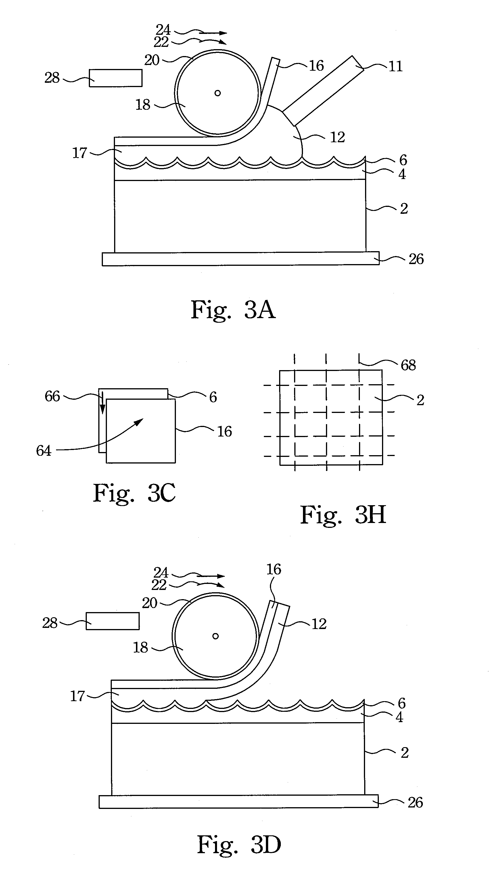
[0066]There will now be described with reference to FIG. 3b a method of manufacture of a surface relief birefringent liquid crystal component which may be performed using the apparatus shown in FIG. 3a. The steps shown in FIG. 3b can be carried out in any order, not limited to the order in which they are described below.

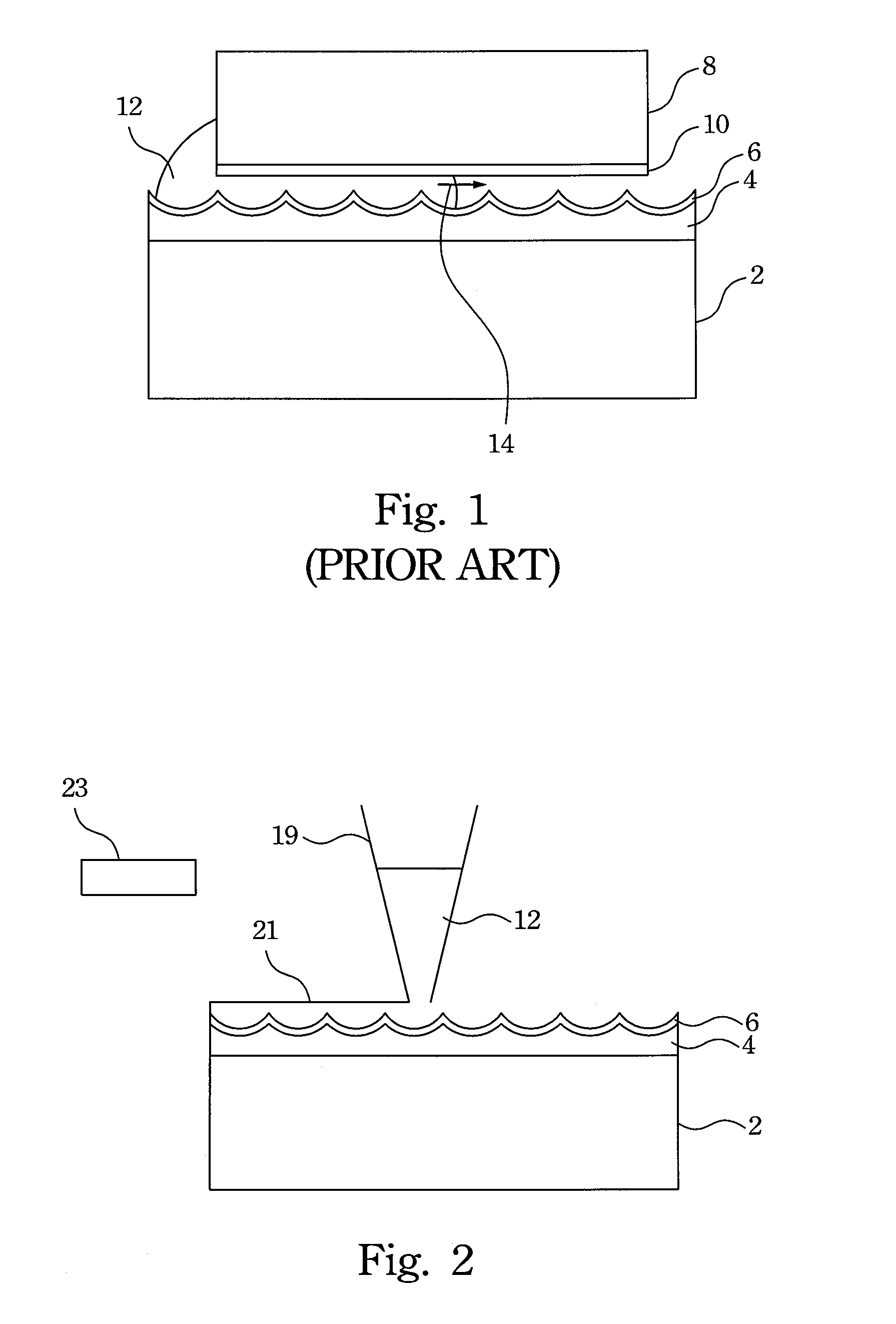
[0067]In step 30, a rigid substrate 2, which may be made of glass or a polymer, has a surface relief layer 4 formed on its surface. The surface relief layer 4 comprises a first material which in this example is isotropic and a polymer. The outer surface of the surface relief layer 4 (uppermost in FIG. 3a) is shaped with a surface relief structure, in this case comprising an array of cylindrical lens surfaces. The substrate 2 may alternatively be semi-rigid or flexible, for example when flatness or dimensional stability of the birefringent liquid crystal component is not critical. The substrate 2 may in some cases be of the same material as the isotropic polymer mater...


PUM


Abstract

Manufacture of a birefringent liquid crystal cell is performed as follows. A layer of isotropic material having an outer surface which is shaped with a surface relief structure and is provided with a liquid crystal alignment property is formed. A flexible sheet having an outer surface provided with a liquid crystal alignment property is formed. A curable birefringent liquid crystal material is applied to one or both of the layer of isotropic material and the flexible sheet. The flexible sheet is applied over the layer of isotropic material with the outer surfaces of the layer of isotropic material and the flexible sheet facing one another with the liquid crystal material therebetween, thereby to form a liquid crystal cell. The liquid crystal material is cured and the flexible sheet is removed from the liquid crystal cell.

Description

RELATED APPLICATIONS[0001]This application is a co-pending application which claims priority to PCT Application No. PCT / GB2007 / 004455, filed Nov. 21, 2007, herein incorporated by reference in its entirely.BACKGROUND[0002]1. Field of Invention[0003]The present invention relates to the manufacture of surface relief birefringent liquid crystal components. Such components are suitable for use in a wide range of applications, including without limitation autostereoscopic 3D displays, brightness enhanced displays, for use in illuminating display devices, particularly transmissive and transflective display systems and as a switching component for use in optical networking.[0004]2. Description of Related Art[0005]Surface relief birefringent optical components are described for example in WO-03 / 015424 and WO-2005 / 006056. A birefringent microlens array is formed from a surface relief interface between an isotropic material and an aligned birefringent liquid crystal material. Light of a first ...

Claims


Application Information

Patent Timeline
14 Jan 2010
Publication
US20100007806A1
IPC
G02F1/1335; G02F1/13; G02B30/28
CPC
G02B5/0215; G02B5/0278; G02B27/2214; G02B5/3016; G02B5/0294; G02B30/28; G02F1/133636; G02B30/27
Inventors
WOODGATE, GRAHAM JOHN; HARROLD, JONATHAN