
Control device for walking assistance device

Active Publication Date: 2010-01-14
HONDA MOTOR CO LTD
View PDF4 Cites 17 Cited by
  • Summary
  • Abstract
  • Description
  • Claims
  • Application Information

AI Technical Summary

Benefits of technology

[0009]According to the first invention, each foot sole installation section connected through each leg link to the seating section is fitted to the foot sole of each leg of the user. Moreover, the driving force of at least one of the actuator for the right leg link and the actuator for the left leg link is controlled so that the force acting on the user from the seating section is maintained at a level of the predetermined lower limit or greater of the upward force. This allows the walking assistance device to perform movements together with the user while preventing the seating section from being away from the user without securing the seating section to the user, independently of the motion pattern that the user is to perform, including a case where the user is to jump.
[0205]Also in this embodiment, it is possible to generate the same effects as in the first embodiment. Moreover, particularly when the device weight compensation force is estimated, it is possible to estimate the device weight compensation force more accurately by using the acceleration detected value detected by the acceleration sensor 80, in addition to the measurement value θ1 of the knee angle of each leg link 3. This thereby enables more accurate control of the raising force to the target raising force.

Problems solved by technology

The walking assisting device, however, easily causes a mismatch between the motion of the leg links and the motion of the walker's legs that the walker desires since the leg links of the walking assisting device move independently of the motion of the walker's legs.
Therefore, the walking assisting device is susceptible to occurrence of disabling the walker to make a walking motion in a manner of moving the legs that the walker desires.
Moreover, it is very difficult for the walker to match the timing of leaving the floor or landing of the walker's leg with the timing of leaving the floor or landing of the walking assisting device when the walker is to jump since the leg link of the walking assisting device moves independently of the motion of the walker's leg.
Accordingly, it is practically impossible for the walker wearing the walking assisting device to jump.
Moreover, the walker's waist secured to the seat causes the walker to have an uncomfortable constrained feeling.
If the walker's waist is not secured to the seat to remove the constrained feeling, the walker's waist is easily detached from the seat when the walker is to jump or the like, and thereafter the walking assisting device is not capable of assisting the walker's motion unless the walker reseats himself or herself.

Method used


Image

  • Control device for walking assistance device
  • Control device for walking assistance device
  • Control device for walking assistance device

Examples


first embodiment

[0043]the present invention will be described below with reference to the accompanying drawings.

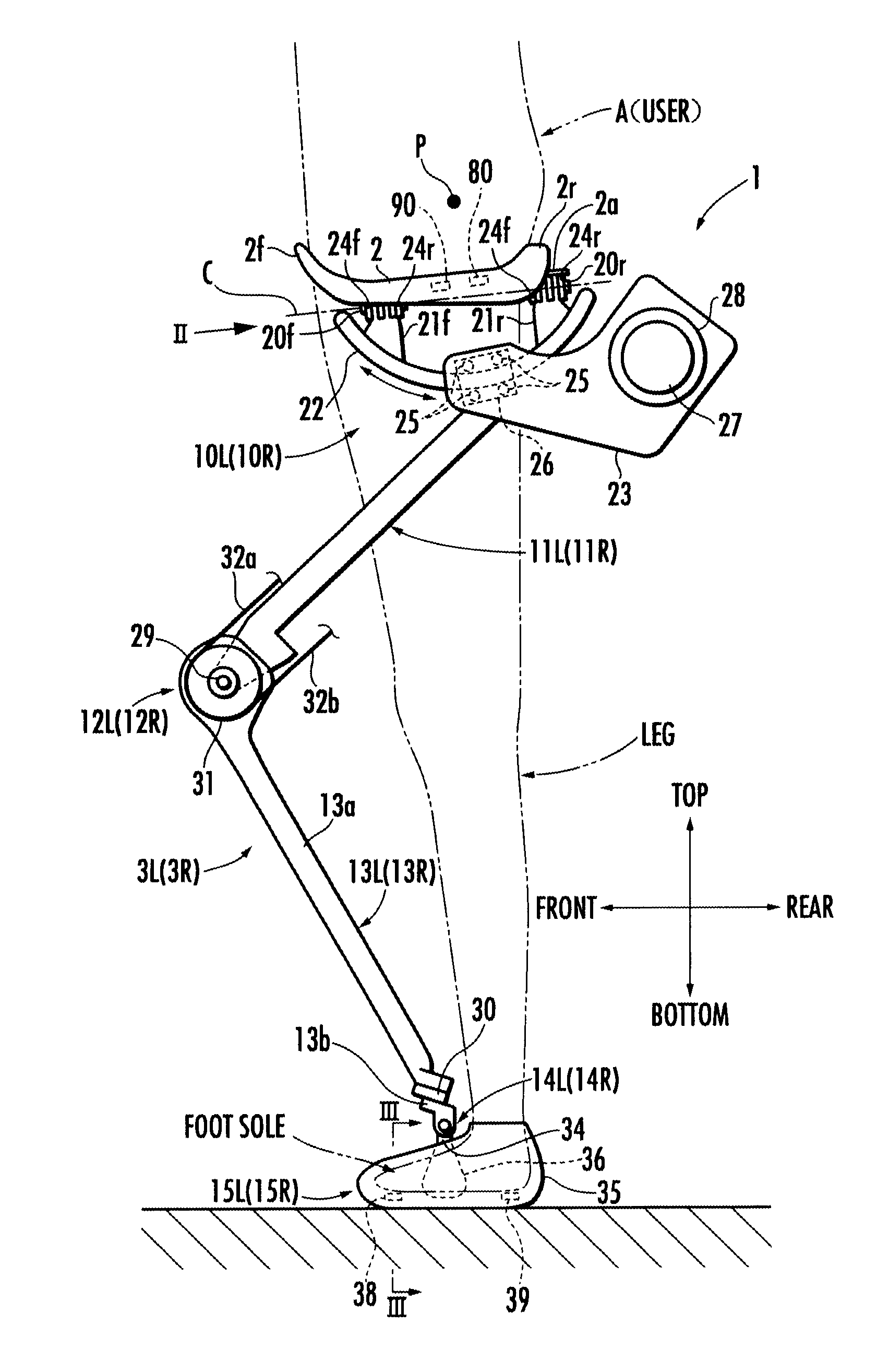
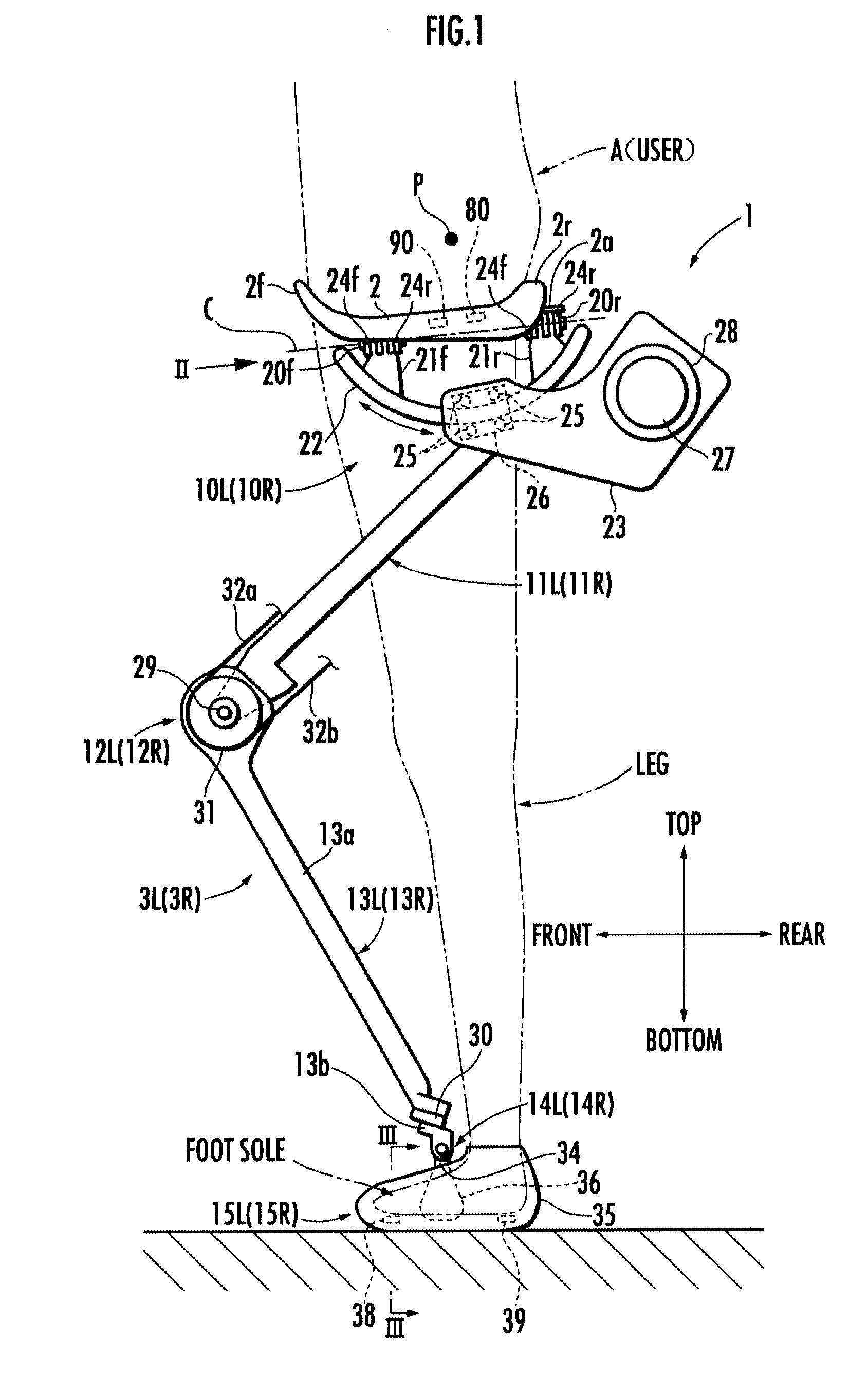
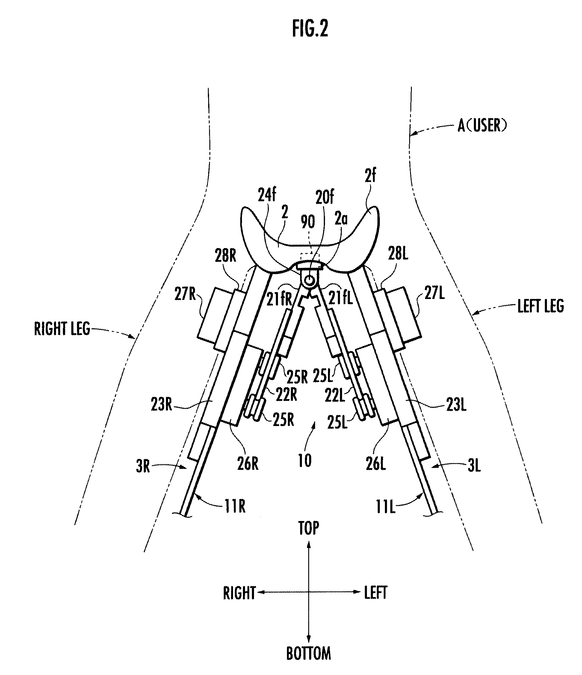
[0044]First, a mechanical structure of the walking assistance device according to this embodiment will be described with reference to FIG. 1 to FIG. 3. FIG. 1 is a side view of the walking assistance device 1, FIG. 2 is a view on arrow taken along line II of FIG. 1, and FIG. 3 is a sectional view taken along line III-III of FIG. 1. The walking assistance device 1 in FIG. 1 to FIG. 3 is shown in a state where the walking assistance device 1 is attached to a user A (indicated by a virtual line). In this instance, the shown user A is standing substantially upright. In FIG. 2, however, the user A is taking a posture of opening his / her legs horizontally for easy understanding of the structure of the walking assistance device 1.

[0045]Referring to FIG. 1 and FIG. 2, the walking assistance device 1 is a weight relief assist device which supports a part of the weight of the user A (which reduces t...

second embodiment

[0049]Moreover, the seating section 2 is secured to a seating section frame 2a provided on the bottom surface of the seating section 2 via a force sensor 90. The force sensor 90 detects the raising force (or its reaction force) and corresponds to an acting force detection means in the present invention. Hereinafter, the force sensor 90 is referred to as a raising force sensor 90. Moreover, an acceleration sensor 80 is attached to the seating section frame 2a. Note that, however, the acceleration sensor 80 is used for a second embodiment described later and thus may be omitted in this embodiment.

[0050]Each leg link 3 includes a thigh frame 11 connected to the seating section frame 2a through a first joint 10, a crus frame 13 connected to the thigh frame 11 through a second joint 12, and a third joint 14 connecting the crus frame 13 to a foot sole installation section 15.

[0051]The first joint 10 of each leg link 3 corresponds to a hip joint of the user A and allows a swing motion arou...


PUM


Abstract

A control device for a walking assistance device includes a seating section on which a user is seated, a pair of left and right foot sole installation sections fitted to the foot soles of the legs of the user, a pair of left and right leg links which connect the seating section to the foot sole installation sections, actuators which drive joints of the leg links, and an acting force detection means which detects force acting on the user from the seating section. The control device controls a driving force of at least one of the actuators according to the detected value of the acting force so that the force acting on the user is maintained at a least at a predetermined lower limit of upward force. Thus, desired user motions, such as jumping can be performed while appropriate force acts on the user from the seating section.

Description

TECHNICAL FIELD [0001]The present invention relates to a control device for a walking assistance device for assisting a user (person) in motion such as walking.BACKGROUND ART [0002]Conventionally, as this type of device, there is known one disclosed in, for example, Paragraphs 0023 to 0030 and shown in FIG. 8 to FIG. 12 of Japanese Patent Application Laid-Open No. Hei 5(1993)-328186 (hereinafter, referred to as Patent Document 1). The walking assisting device shown in FIG. 8 to FIG. 12 of Patent Document 1 has a seat to which a walker's waist is fixed, and the walking assisting device is supported on a floor by four leg links extending from the seat. The leg links are not attached to the walker's legs so as to be capable of moving independently of the walker's legs.[0003]Additionally, the walking assisting device has a sensor (a pressure sensor or 6-axial force sensor) for detecting force acting between the seat and the walker to drive joints of the leg links of the walking assistin...

Claims


Application Information

Patent Timeline
IPC IPC(8): A61F2/48
CPCA61H3/008B25J9/0006A61H3/00A61H2201/1215A61H2201/5084A61H2201/1642A61H2201/1676A61H2201/5061A61H2201/5069A61H2201/1633
Inventor IKEUCHI, YASUSHI
Owner HONDA MOTOR CO LTD
Learn More