
Block and tackle balance assembly with rotatable shoe

Inactive Publication Date: 2010-01-21
VISION INDS GROUP
View PDF9 Cites 2 Cited by
  • Summary
  • Abstract
  • Description
  • Claims
  • Application Information

AI Technical Summary

Benefits of technology

[0011]The housing may be in many different cross-sectional shapes, bit is preferably a U-shaped channel. The block and tackle pulley arrangement may be installed within the housing of the balance assembly using a number of different fastening systems, including but not limited to screws, nut and bolts, etc. but in a preferred embodiment, a pin is used to fix the upper rectangular frame to the housing. The lower diamond shaped frame of the block and tackle pulley arrangement is biased relative to the housing by attaching a helical spring member, preferably having hooked open ends, to a pin that spans the housing sidewalls, and to an orifice in the diamond shaped frame. The housing may also facilitate attachment of the rotatable shoe.
[0013]This rotation ability of the shoe permits installation of the Block and Tackle Balance Assembly with Rotatable Shoe into a window frame at any stage of the window assembly sequence, permitting the balance assembly to be easily installed at a more advantageous time in the assembly sequence.

Problems solved by technology

If the counterweight were sized excessively, the sash member would be difficult to close and would tend to not remain shut.
Conversely, if the counterweight were undersized, the sash member would be difficult to open, and would tend to not remain open.
But a serious deficiency of these inventions—because of the limited envelope of the frame, and the size of the “shoe” on such balance assemblies that must necessarily nest within that envelope—is the limitation that the balance assemblies must be fitted into the frame at an early stage of the window assembly sequence by using an intricate installation procedure.

Method used


Image

  • Block and tackle balance assembly with rotatable shoe
  • Block and tackle balance assembly with rotatable shoe
  • Block and tackle balance assembly with rotatable shoe

Examples


Embodiment Construction

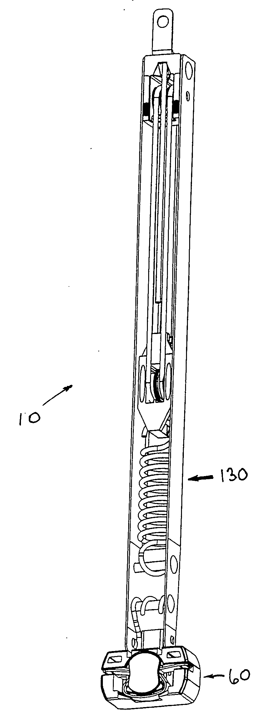
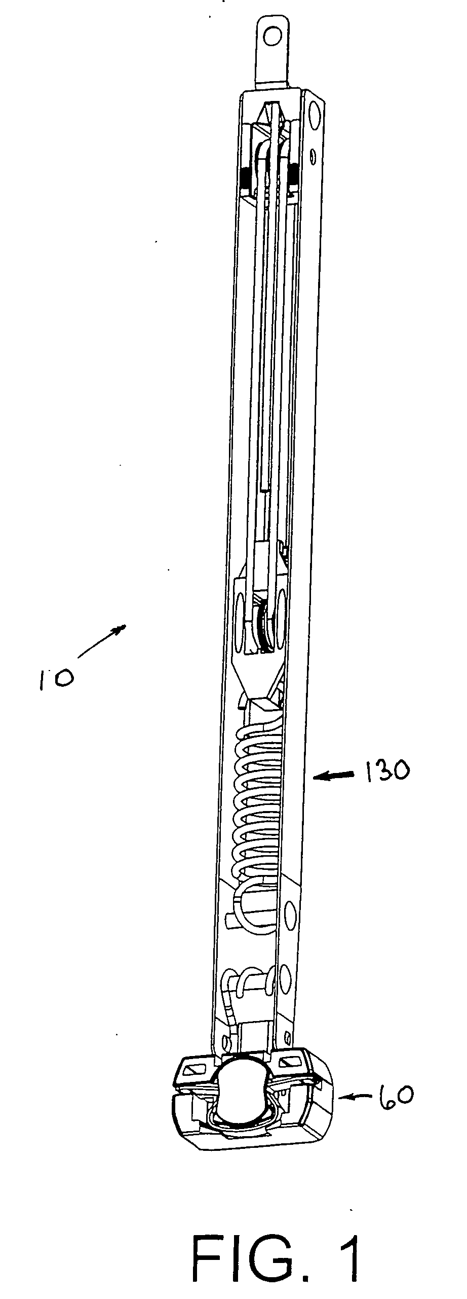
[0034]The Block and Tackle Balance Assembly with Rotatable Shoe 10 is shown in FIG. 1. The block and tackle balance assembly with rotatable shoe 10 is comprised, in a preferred embodiment, of Housing Assembly 130, and Shoe Assembly 60.

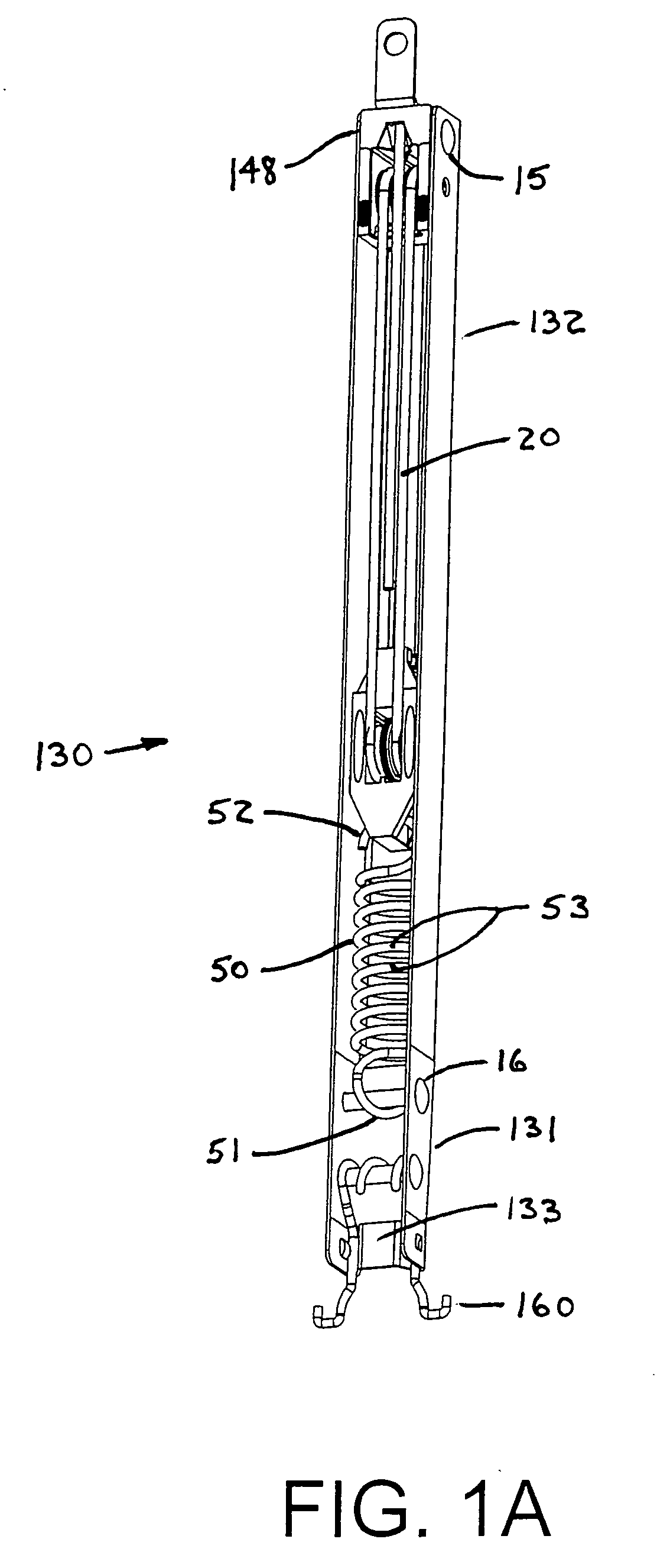
[0035]The housing assembly 130 is comprised of housing 131, Hook Means 160, a pulley arrangement 20, Helical Member 50, and Pins 15 and 16 (see FIGS. 1, 4, and 8). The pulley arrangement 20 (see FIG. 2) could include of a pulley, but in the preferred embodiment is a block and tackle. The block and tackle pulley arrangement 20 of the preferred embodiment includes an interconnection means 21. The interconnection means 21 may be, but is not limited to, a cord, string, a cable, a chain, etc.

[0036]The block and tackle pulley arrangement 20 may also include frame 24 with a cavity 29 in which the frame 24 is capable of pivotally mounting a first upper pulley 25 and a second upper pulley 26. Frame 24 may be in many different shapes, but in a preferred embodime...


PUM


Abstract

A balance assembly for a sliding sash window, where a spring-loaded pulley arrangement is interconnected between the window frame and the window, to counter the weight of the window, and permit ease of opening and closing the window. The spring-loaded pulley arrangement is located within a housing, which also facilitates attachment of the shoe. The shoe of this balance assembly being rotatable between a first and a second position to permit fitting the assembly into the side of the window frame, when the shoe is in the first position, and to permit final installation of the assembly when the shoe in the second position. The shoe is retained in the first and second positions by detents. This rotatable shoe feature permitting installation, of the Balance Assembly of this invention, into a window frame at later stages of the window assembly sequence.

Description

FIELD OF THE INVENTION[0001]This invention relates to a balance system for use in a pivotable, sliding window assembly of a sash window, and more particularly to a block and tackle balance assembly with a rotatable shoe.BACKGROUND OF THE INVENTION[0002]A sash window is comprised of one or more moveable panels or sashes, where each sash forms a frame that may hold multiple panes of glass, and both sashes are themselves mounted into a window frame. A “single hung” sash window ordinarily opens by having one sash member, typically the lower sash, sliding vertically relative to the window frame. An arrangement where both sash members can slide vertically is termed a “double hung sash window” or double hung window. For applications in buildings with tall openings, such as for church windows, triple and quadruple-hung windows have been utilized to accommodate the opening.[0003]Each sash member, being comprised of multiple panes of glass housed in a wood frame of the sash, would be quite he...

Claims


Application Information

Patent Timeline
IPC IPC(8): E05D13/00E06B3/32
CPCE05D13/1207E05D15/22Y10T16/6298Y10T16/64E05Y2900/148
Inventor LIANG, LUKELIANG, TONGCHEN, DAVID
Owner VISION INDS GROUP
Features
  • Generate Ideas
  • Intellectual Property
  • Life Sciences
  • Materials
  • Tech Scout
  • Unparalleled Data Quality
  • Higher Quality Content
  • 60% Fewer Hallucinations
Learn More