Centrifugal separator

a centrifugal separator and centrifugal technology, applied in centrifuges, separation processes, machines/engines, etc., can solve the problems of reducing the separation efficiency of the separation disc, and achieve the effects of less rigidity, increased pumping action, and increased gas entrainmen

Active Publication Date: 2010-01-21
ALFA LAVAL CORP AB
View PDF26 Cites 51 Cited by
  • Summary
  • Abstract
  • Description
  • Claims
  • Application Information

AI Technical Summary

Benefits of technology

[0018]According to a further embodiment of the invention, the spacing elements in any given ring are displaced in the circumferential direction relative to the spacing elements in an adjacent ring. Hereby it is provided further assurance of even spacing throughout the interspaces.
[0019]According to a further embodiment of the invention, at least the radially outer parts of the interspaces lack said spacing elements. In this case the radially outer parts of the interspaces are fully open for flow of the gas in both the radial direction and the circumferential direction. This may with advantage be applied in the case of rigid separation discs whose rigidity ensures even spacing in the radially outer parts, i.e. no substantial deformation of the separation discs occur during operation of the centrifugal separator.
[0020]According to a further embodiment of the invention, the separation discs have at their radially inner parts of the interspaces a plurality of elongate spacing elements. Situating such spacing elements in the radially inner parts of the interspaces results in open flow of the gas in the radially outer parts of the interspaces. At the same time, such elongate spacing elements cause an increased pumping action on the rotor and increase the entrainment of the gas in the rotation of the rotor.
[0021]According to a further embodiment of the invention, the separation discs at their radially outer parts of the interspaces have only punctiform spacing elements. This may with advantage be applied in the case of separation discs made of less rigid material, wherein the spacing elements provide assurance of even spacing throughout the interspaces in the radially outer parts and at the same time provide free flow of the gas in both the radial direction and the circumferential direction.
[0022]According to a further embodiment of the invention, the separation discs at their both radially outer and inner parts of the interspaces have only punctiform spacing elements, thereby providing—in a simple manner—even interspaces in the case of less rigid separation discs.
[0023]According to a further embodiment of the invention, the separation discs have planar portions which comprise spacing elements, the conical portions of the separation discs lacking said spacing elements at their both radially outer and inner parts of the interspaces. Accordingly the interspaces are fully open for flow of the gas in both the radial direction and the circumferential direction throughout the interspaces. This can with advantage be applied in the case of separation discs with high rigidity which provides assurance of even interspaces in both the radially outer and inner parts, i.e. no substantial deformation of the separation discs occur during operation of the centrifugal separator.

Problems solved by technology

This means that not all of the surface of the separation disc is used for separation of particles, with consequently reduced separation efficiency of the separation disc.

Method used


Image

  • Centrifugal separator
  • Centrifugal separator
  • Centrifugal separator

Examples


second embodiment

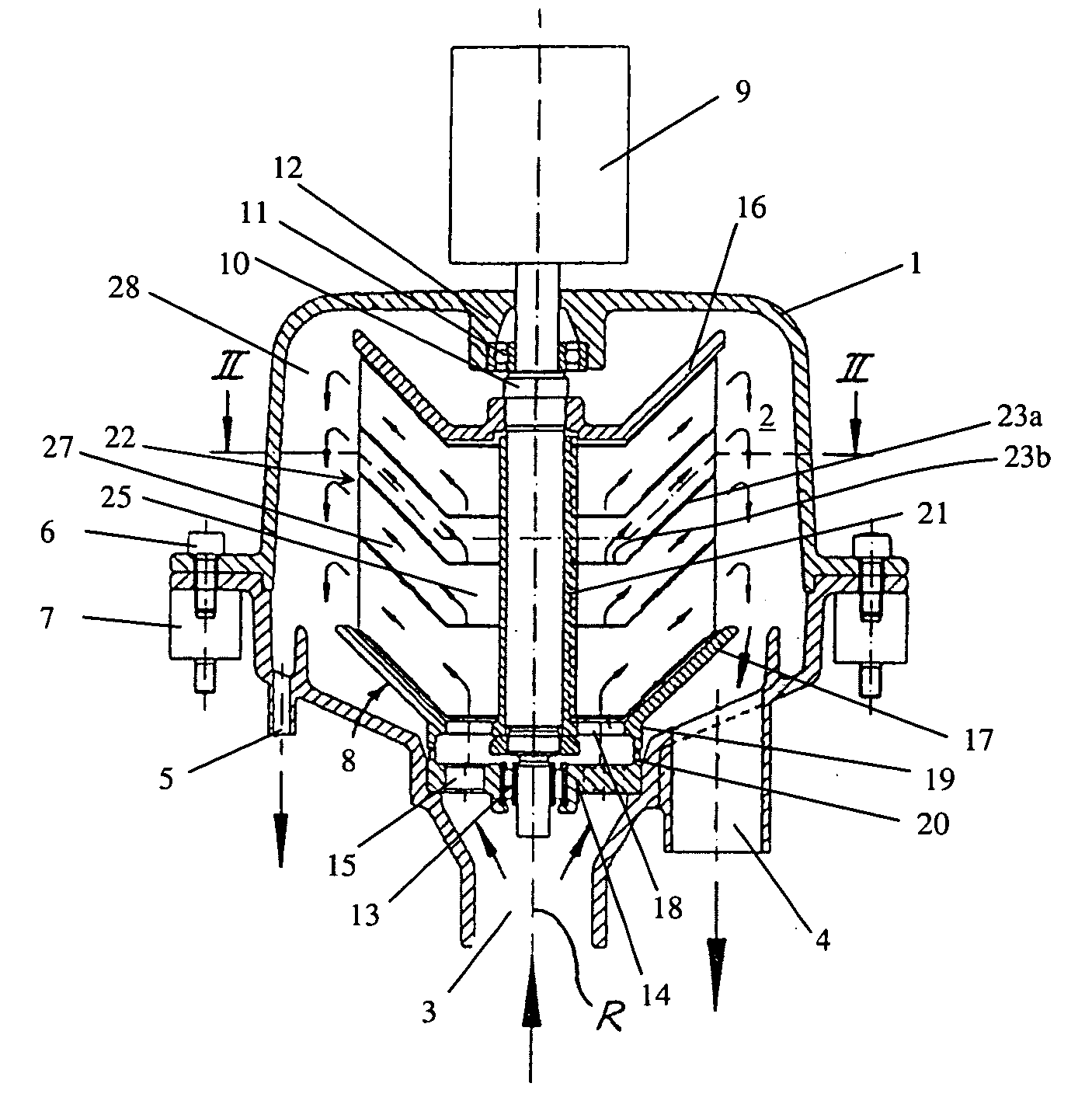
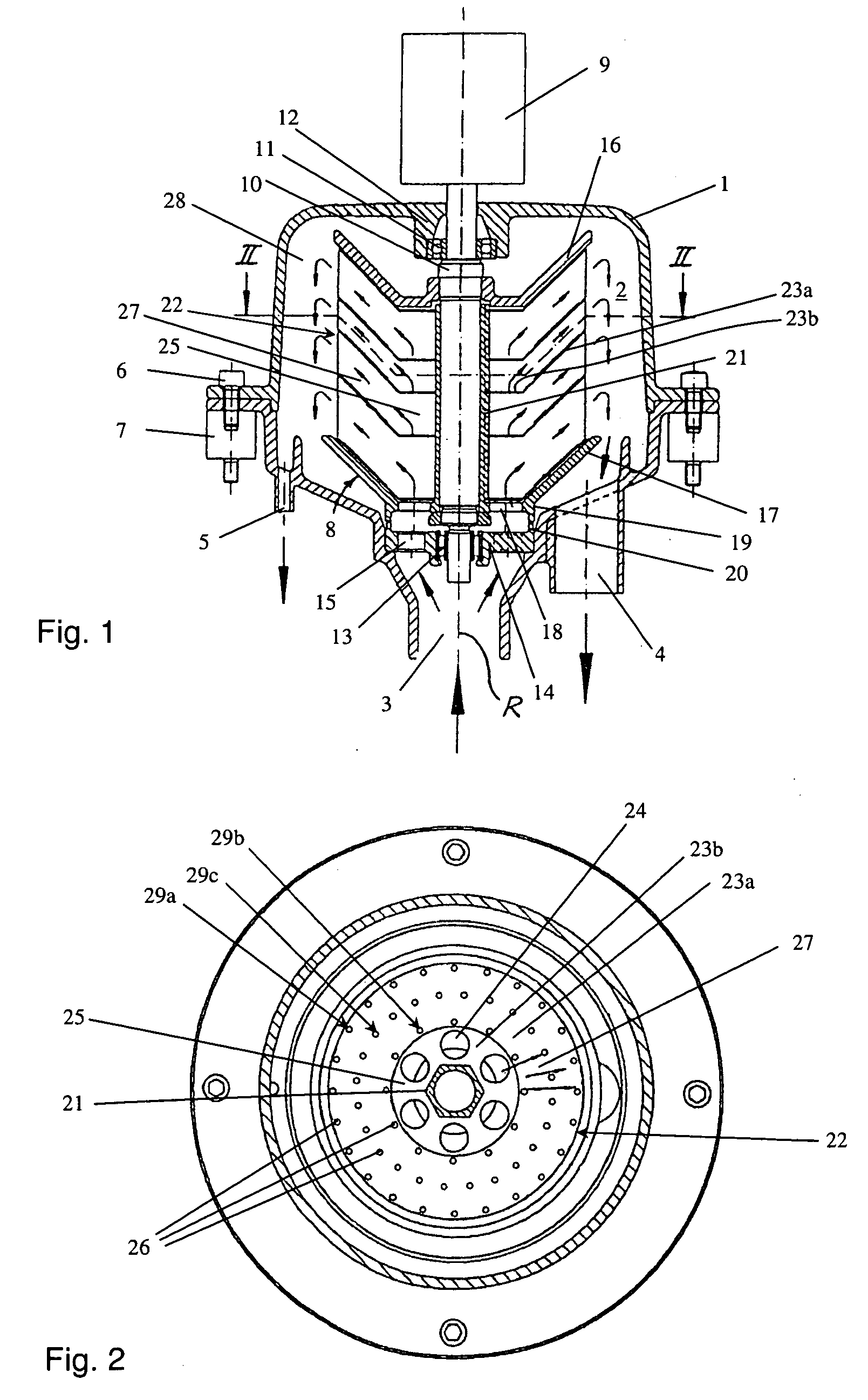
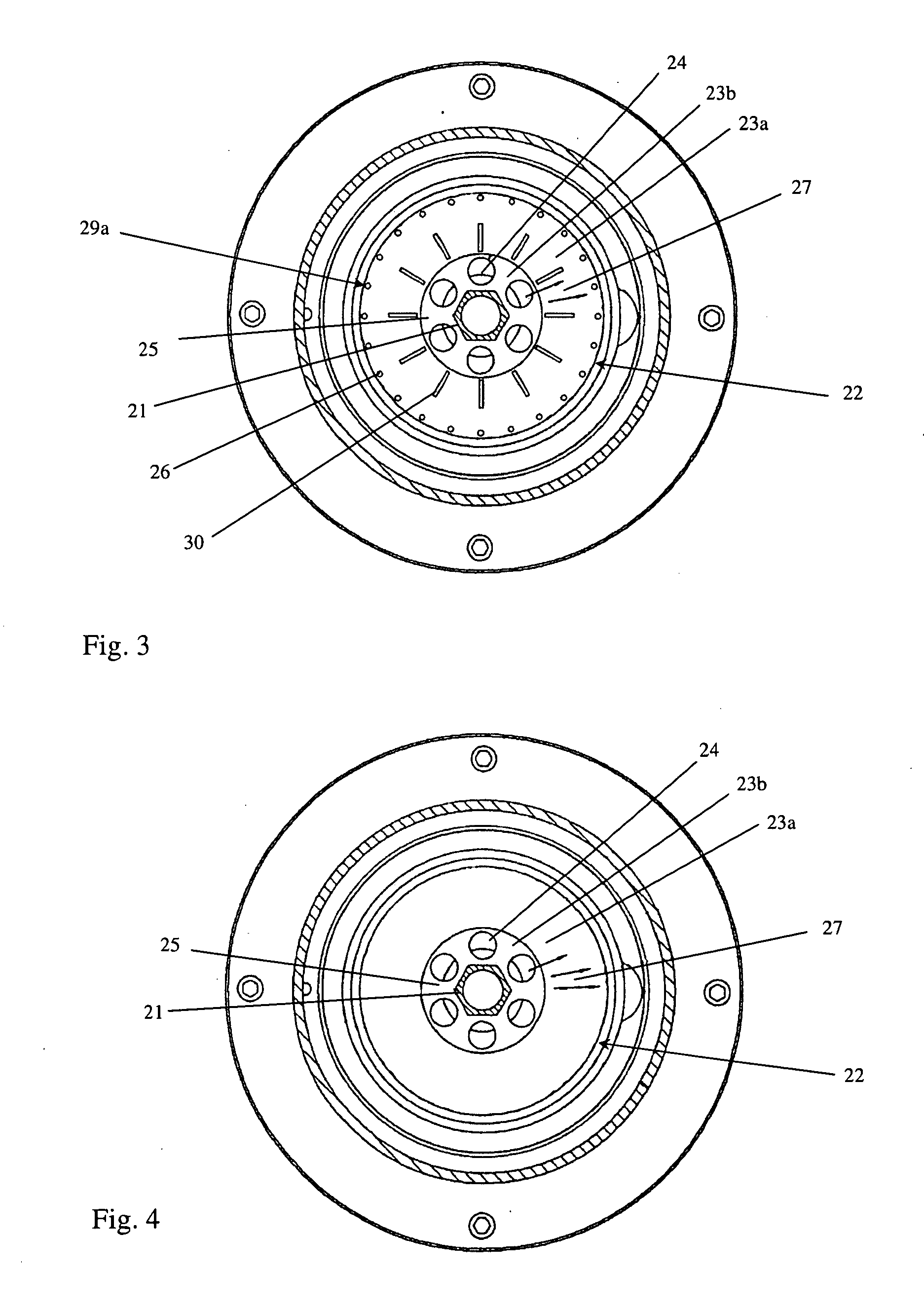
[0038]FIG. 3 shows—according to the invention—the side of a separation disc 22 which faces upwards in FIG. 1. This separation disc 22 is provided on its inside with a plurality of punctiform spacing elements 26 evenly distributed in a ring 29a close to the radially outer circumferential edge of the separation disc, wherein a radially inner part of the conical portion of the separation disc is provided with a plurality of elongate spacing elements 30. The interspace 27 is thus open in at least its radially outer part for flow of the gas in the circumferential direction. Hereby the elongate spacing elements 30 do not block flow of the gas in the circumferential direction in the radially outer parts of the interspaces. The formation of said inactive regions on the surface of the separation disc is thus prevented. In this embodiment of the invention, the separation disc thus comprises a plurality of elongate spacing elements which extend in a rectilinear manner in the radial direction. ...

third embodiment

[0039]FIG. 4 shows—according to the invention—the side of a separation disc 22 which faces upwards in FIG. 1. This separation disc 22 has a completely smooth surface, i.e. a surface with no spacing elements, along at least the conical portion 23a of the separation disc. The interspaces 27 are thus open for flow of the gas in the circumferential direction in both the radially outer parts and the radially inner parts of the interspaces. Hereby the separation disc has no spacing elements that might block flow of the gas in the circumferential direction, whereby the formation of said inactive regions on the surface of the separation disc is prevented. In this embodiment, the spacing elements 30 may be incorporated in the planar portion 23b of the separation disc or alternatively comprise separate elements disposed in the planar portion 23b of the separation disc between mutually adjacent separation discs. It is also possible to conceive of the separation discs being stacked on a rotor w...


PUM

PropertyMeasurementUnit
heightaaaaaaaaaa
distanceaaaaaaaaaa
angleaaaaaaaaaa

Abstract

The invention relates to a centrifugal separator for cleaning of gas from solid or liquid particles suspended therein which are of greater density than the gas. A main object of the present invention is to accomplish a centrifugal separator which does not have said inactive regions and thereby achieves efficient separation of particulate contaminants from a gas. This object is achieved by the centrifugal separator initially defined, which is characterised in that the interspaces between the separation discs at least at their radially outer parts are substantially open for flow of the gas in the circumferential direction and that mutually adjacent separation discs are arranged at mutual spacing such that rotation of the rotor causes a pumping action in the interspaces, which pumping action drives the gas from the gas inlet, through the interspaces between the separation discs and out via the gas outlet.

Description

CROSS REFERENCE TO RELATED APPLICATION[0001]This application claims priority to Swedish Patent Application No. 0801695-8 filed on Jul. 16, 2008, the subject matter of this patent document is incorporated by reference herein in its entirety.FIELD OF THE INVENTION[0002]The present invention relates to a centrifugal separator for cleaning of gas from solid or liquid particles suspended therein which are of greater density than the gas. The centrifugal separator comprises a rotor housing which delimits a separation chamber and which has a gas inlet to the separation chamber and a gas outlet from the separation chamber. The centrifugal separator further comprises a rotor which by means of a driving device is rotatable around a rotational axis and which is adapted, during operation, to bring the gas into rotation in the separation chamber, wherein the rotor comprises a stack of frustoconical separation discs which are disposed coaxially with one another and concentrically with the rotatio...

Claims


Application Information

Patent Timeline
Patent Type & Authority Applications(United States)
IPC IPC(8): B01D45/14
CPCB01D45/14B04B2005/125B04B7/14B04B5/12B04B1/08F01M13/04
Inventor SZEPESSY, STEFANTORNBLOM, OLLE
Owner ALFA LAVAL CORP AB
Why Eureka
Try Eureka