
Method of refurbishing a seal land on a turbomachine transition piece and a refurbished transition piece

a technology of turbomachine and transition piece, which is applied in the field of turbomachine, can solve the problems of increasing the number of refurbishing, reducing the service life of the seal land, and reducing the service life of the turbine, and achieves the effect of providing abrasion resistance to the seal land

Active Publication Date: 2010-01-21
GENERAL ELECTRIC CO
View PDF5 Cites 13 Cited by
  • Summary
  • Abstract
  • Description
  • Claims
  • Application Information

AI Technical Summary

Benefits of technology

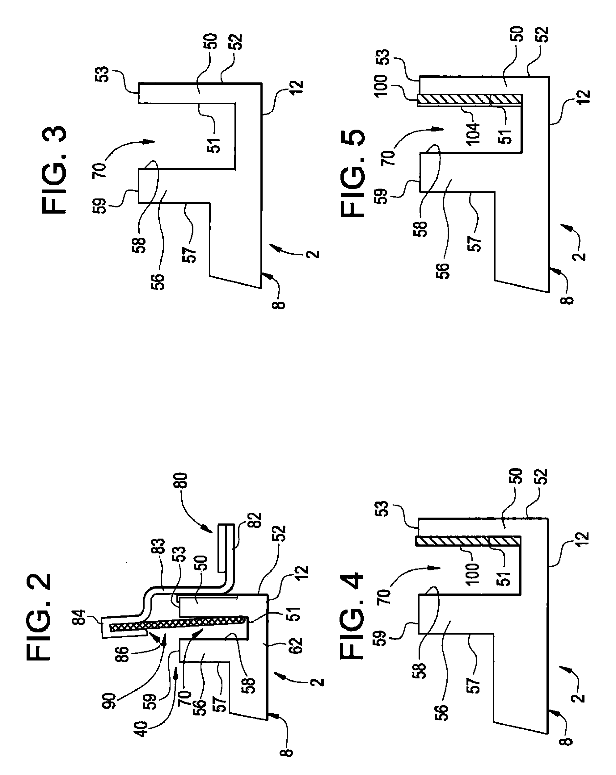
[0006]In accordance with another exemplary embodiment of the present invention, a refurbished transition piece for a turbomachine includes a main body having a first end that extends to a second end through an intermediate portion. A seal land extends about a portion of at least one of the first and second ends. The seal land includes first and second opposing side walls that are joined by a third wall to collectively define a slot. A wear strip is bonded to at least one of the first, second and third walls, and a slot protector is bonded to the wear strip. The slot protector provides abrasion resistance to the seal land.
[0007]The above described exemplary embodiments result in enhanced operating efficiencies for turbomachines. That is, the wear strips provide additional wear resistance for the seal land thereby increasing an overall service life of the transition piece. More specifically, by adding a slot protector on the seal land, repeated welding steps previously required to provide renewed wear protection are eliminated. Eliminating welding steps also reduces any thermal cycling, which, over time, will weaken the seal land.

Problems solved by technology

Without proper sealing between the transition piece and the turbine, compressor cooling air could pass into the turbine resulting in performance and efficiently losses.
Over time, the vibrations / deflections and / or travel cause the seal to abrade a seal land portion of the transition piece resulting in wear.
Moreover, there are a finite number of refurbishing cycles that can be performed before the seal land will become fatigued.
Refurbishing a seal land in this manner is very expensive, requiring up to 300 hours / set, and only extends the life of a transition piece a finite period.

Method used


Image

  • Method of refurbishing a seal land on a turbomachine transition piece and a refurbished transition piece
  • Method of refurbishing a seal land on a turbomachine transition piece and a refurbished transition piece
  • Method of refurbishing a seal land on a turbomachine transition piece and a refurbished transition piece

Examples


Embodiment Construction

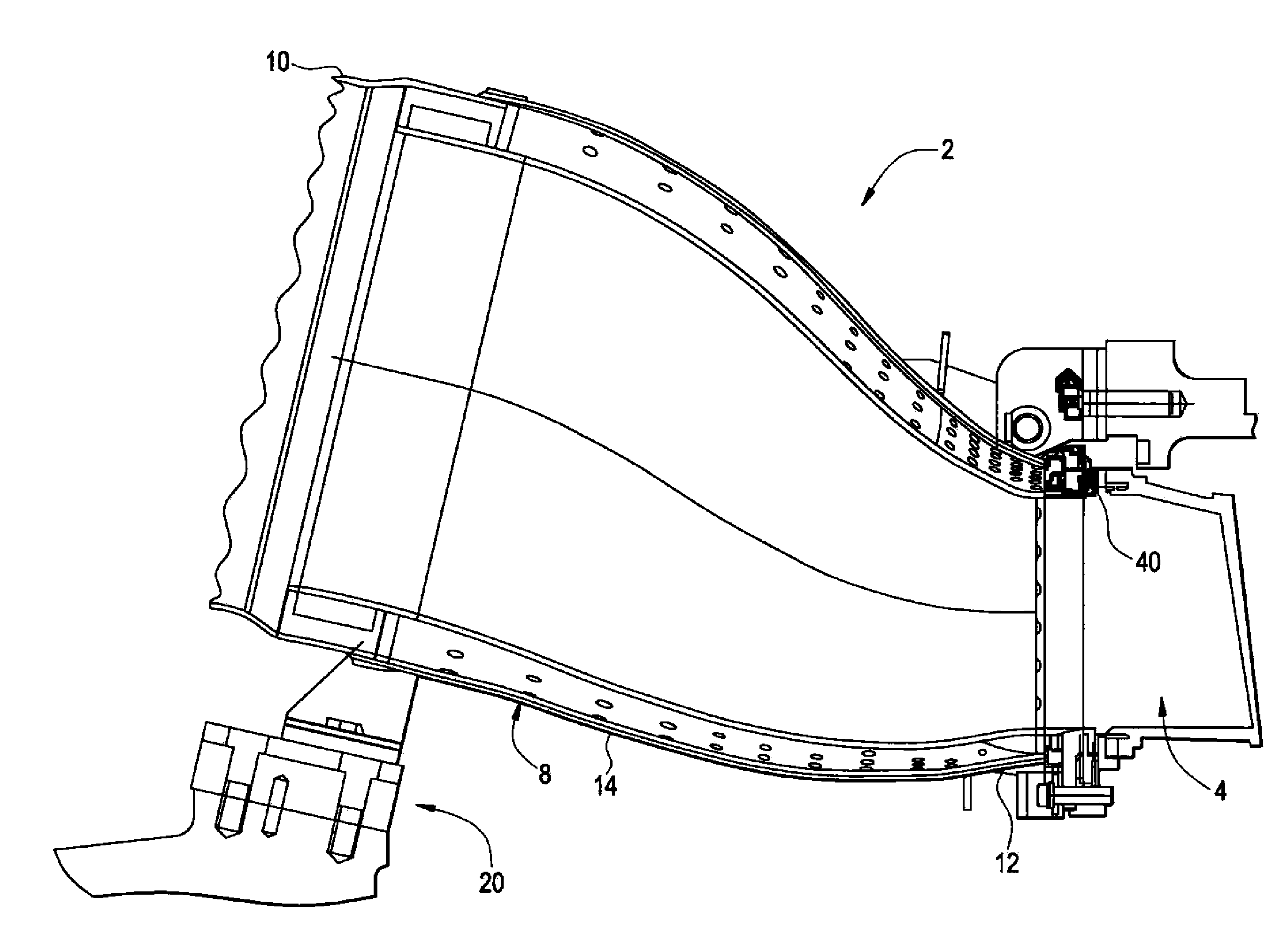
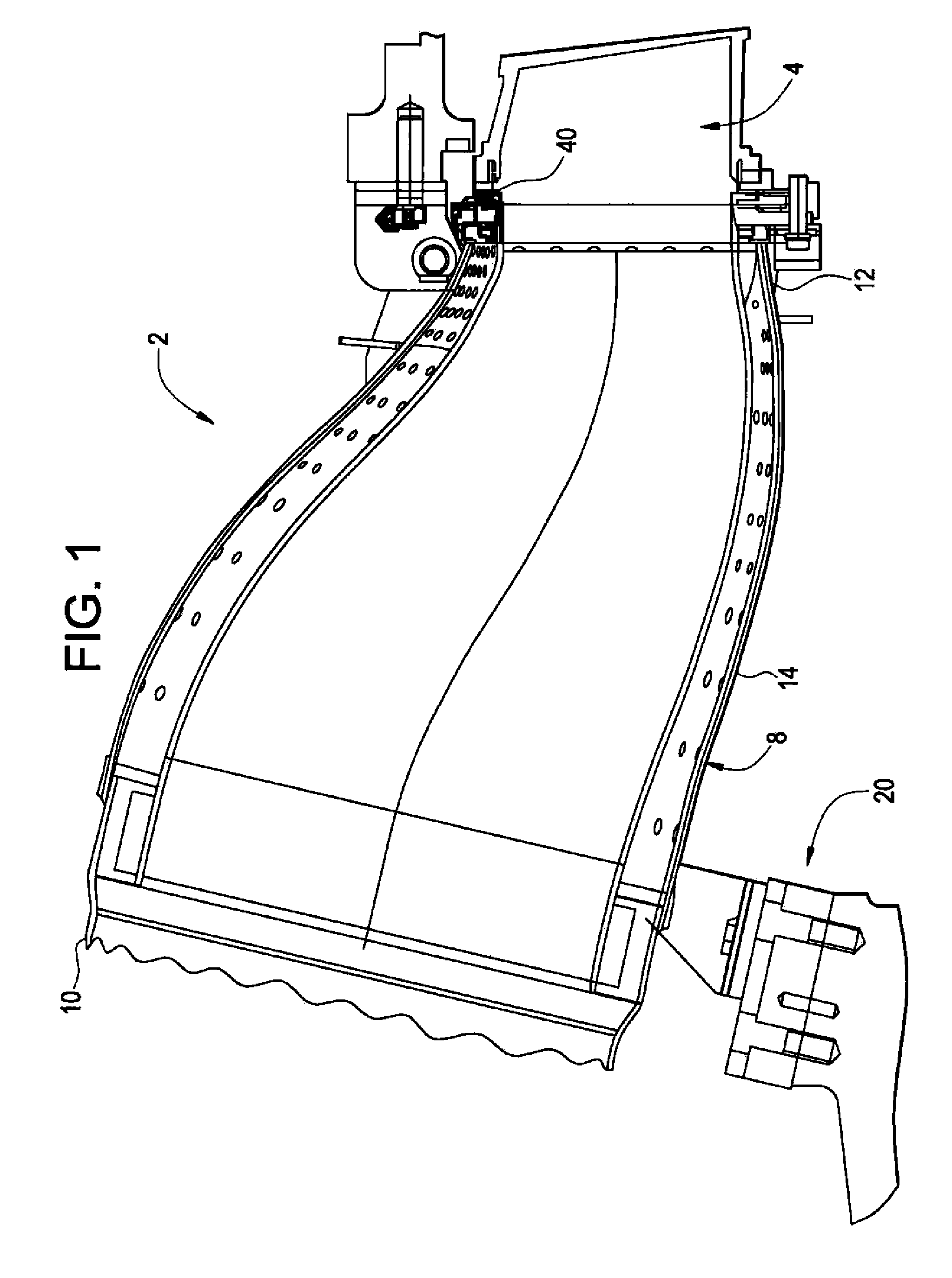
[0014]With initial reference to FIG. 1, a transition piece (TP) for a turbomachine, for example a gas turbine engine, is indicated generally at 2. Transition piece 2 is operatively connected between a turbine combustor portion (not shown) and a first turbine stage 4. Towards that end, transition piece 2 includes a main body 8 having a first end 10 that extends to a second end 12 through an intermediate portion 14. In accordance with one aspect of the exemplary embodiment, transition piece 2 is formed from a nickel-based alloy such as, but not limited to, NIMONIC® 263. In the exemplary embodiment shown, first end 10 of transition piece 2 is supported upon the gas turbine by a forward mount 20 while second end 12 connects to first turbine stage 4 through a picture frame or seal land 40 establishing a turbine interface (not separately labeled).

[0015]As best shown in FIG. 2, seal land 40 includes a first side wall 50 having a first surface 51, a second surface 52 and a third or connecti...


PUM

PropertyMeasurementUnit
Thicknessaaaaaaaaaa
Thicknessaaaaaaaaaa
Widthaaaaaaaaaa

Abstract

A method of refurbishing a seal land on a transition piece of a turbomachine includes applying a wear strip to a wall surface of the seal land, and covering the wear strip with a slot protector.

Description

BACKGROUND OF THE INVENTION[0001]Exemplary embodiments of the invention relate to the art of turbomachines and, more particularly, to a method of refurbishing a seal land on a turbomachine turbine transition piece.[0002]In general, turbomachines, particularly gas turbine engines, combust a fuel / air mixture to release heat energy to form a high temperature gas stream that is channeled to a turbine section via a hot gas path. More specifically, a compressor compresses incoming air to a high pressure. The high pressure air is delivered to a combustion chamber to mix with fuel and form a combustible mixture. The combustible mixture is then ignited to form a high pressure, high velocity gas that is passed through a transition piece into a first stage of a turbine. The turbine converts thermal energy from the high temperature, high velocity gas stream to mechanical energy that rotates a turbine shaft. The turbine shaft is coupled to and drives the compressor and also other machinery such ...

Claims


Application Information

Patent Timeline
IPC IPC(8): F01D9/02B23P6/00
CPCB23P6/005F01D9/023Y10T29/49238F05D2240/55Y10S277/94F05D2230/80
Inventor JOHNSON, JERE ALLENKALIDAS, PRAHLAD
Owner GENERAL ELECTRIC CO
Learn More