
Hanger unit and collecting box with it

Inactive Publication Date: 2010-01-21
SUNG BU KYOUNG
View PDF14 Cites 9 Cited by
  • Summary
  • Abstract
  • Description
  • Claims
  • Application Information

AI Technical Summary

Benefits of technology

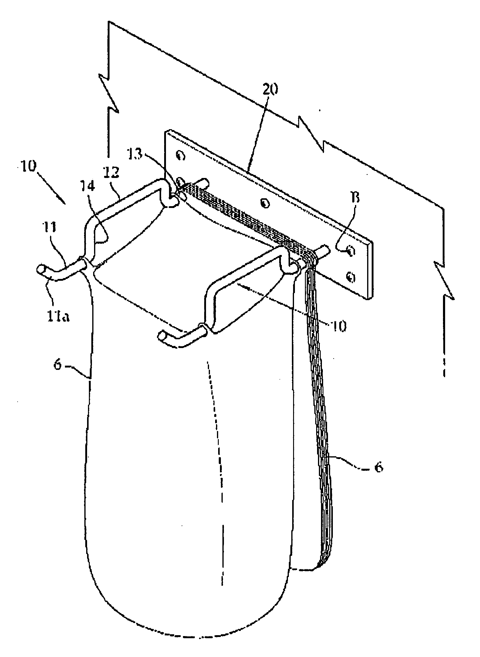
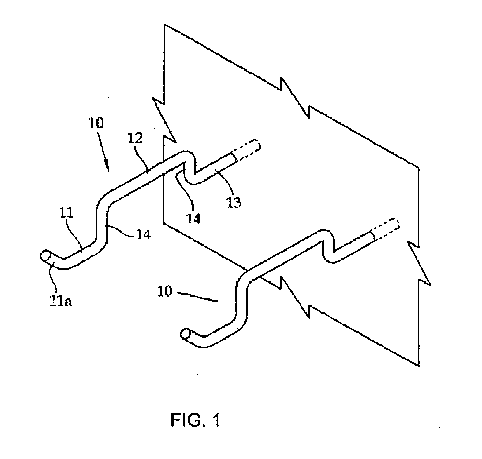
[0006]It is another object of the present invention to provide a hanger for a collection bag and a collection box having the same in which a pair of hangers are installed upright with a regular interval between the same, and a collection box inputting and loading are easy, and four protrusions are formed at a pair of hangers by bending the hangers upwards. Four punched openings of the loaded collection bag are hung by the protrusions, so that the bag is substantially opened with a certain tension.
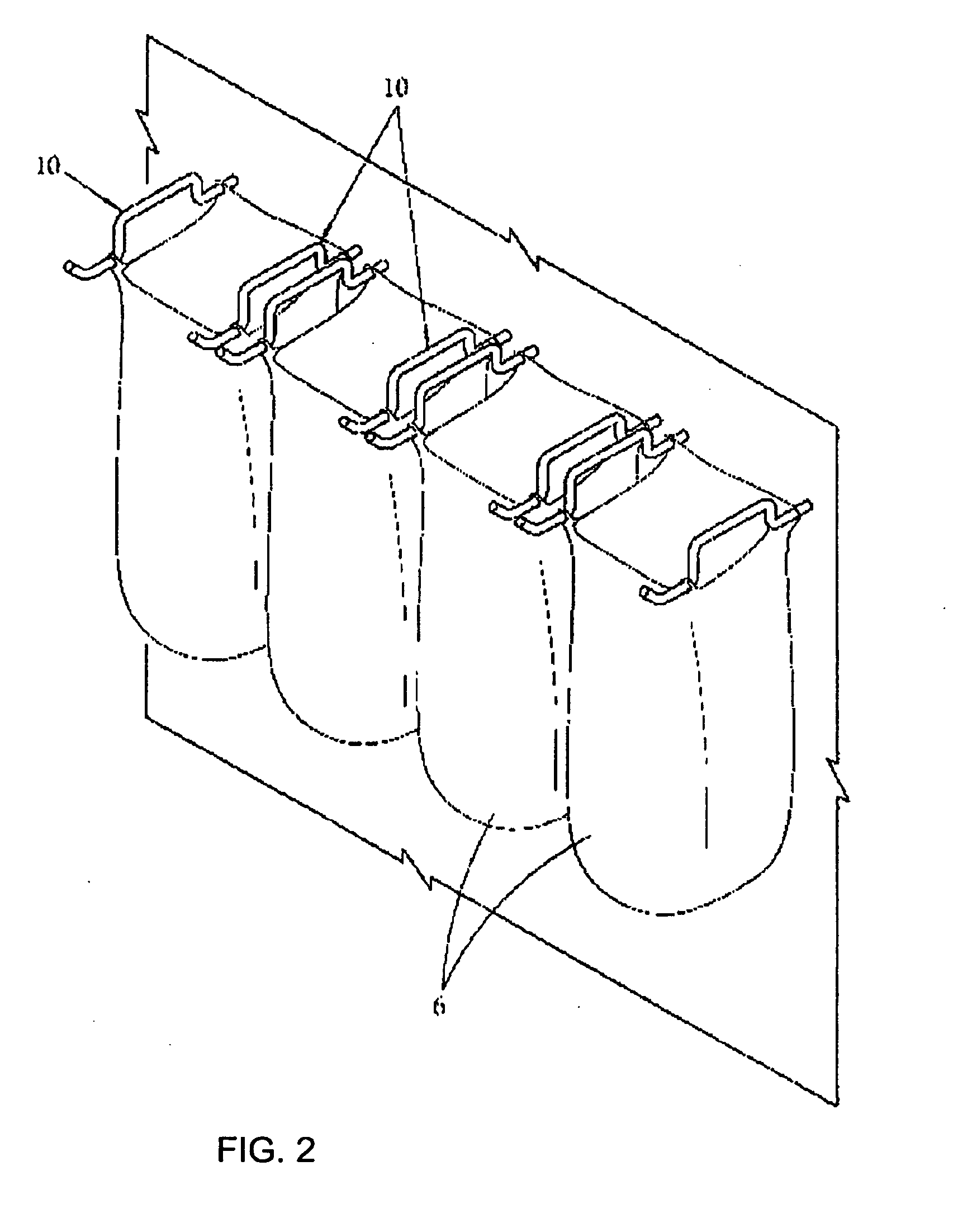
[0007]It is further another object of the present invention to provide a hanger for a collection bag and a collection box having the same in which as the hangers are bent upwards, multiple collection bags are loaded and unfolded easily with the assistance of the protrusions, so that it is possible to easily store recyclable items and waste which are continuously used in life. In addition, since the intervals between the hangers are constant, various kinds of plastic bags or pockets, which are not specially manufactured, but currently available in the markets, can be used.
[0009]It is still further another object of the present invention to provide a hanger for a collection bag and a collection box having the same in which an escaper prevention part provided at a front end of the opening of the hanger is bent upward for thereby enhancing an easier insertion of the collection bag. Even when an interval of the openings of the collection bag is greater by a careless work, it is possible to prevent an escape of the collection bag.
[0011]In the present invention, longitudinal protrusions are formed by vertically bending a pair of hangers. The lengths of the use parts of the hangers are same as the intervals between the hangers. It is easy to move without resistance or friction for an insertion, loading, unfolding and removal when the collection bag with punched openings are disposed on the hangers. Since four longitudinal protrusions 14 are formed, four openings of the collection bag are caught by four longitudinal protrusions of the collection bag hanger 40, so that a collection bag can be unfolded in a square shape. Since the intervals between the hangers 10 are constant, various collection bags can be used irrespective of the kinds of bags such as a meter-rate bag, a plastic bag, and a pocket which are currently available in the market only when the surrounding of the collection bag is above ¼ of the interval between the hangers. Even when the punched opening intervals or punched openings are relatively larger due to a careless work, since there are provided the longitudinal protrusions 14 having relatively higher heights, there are not problems when the collection bag is used. In the present invention, the escape prevention part formed at the front end of the opening of the hangers is upwardly bent, an insertion of the collection bag is enhanced. Even the intervals of the punched openings are larger in the collection bag due to a careless work, it is possible to prevent an escape of the front side of the collection bag from the hangers (external escape of the hanger). Namely, it is possible to use a collection bag larger than the size of the collection box.
[0012]In the collection bag hanger 40 according to the present invention, since the meter-rate system standard bag may be punched, unfolded and used in case of waste, it is not needed to use the collection bag twice for thereby saving a natural resource.
[0013]In addition, a collection bag hanger according to the present invention has a simple structure. It can be easily mounted on a wall or can be installed in the interior of the collection box. The collection box having various shapes and sizes can be made with lower cost in the present invention.

Problems solved by technology

When a punched collection bag is inputted into an opening of the hanger 1, it cannot pass through a rounded portion 4 with a relatively larger interval, so that an insertion and loading are not easy.
Even when a collection bag has been inputted by passing through the rounded portion, a collection bag cannot be hung in a fully unfolded shape.
So, it is impossible to hang and unfold the collection bag without an additional device.
As a result, even when a meter-rate system bag, a plastic bag, or a pocket has an accurate punched opening, it cannot be reliably inputted and hung by a conventional collection bag hanger.

Method used


Image

  • Hanger unit and collecting box with it
  • Hanger unit and collecting box with it
  • Hanger unit and collecting box with it

Examples


Embodiment Construction

[0021]To achieve the above objects, in a collection box hanger which can support a plurality of collection bags for collecting waste or recyclable items, there is provided a collection bag hanger which comprises an opening for receiving a collection bag; a use part which is bent upwards for forming a longitudinal protrusion and allows a collection bag, which will be used, to be caught by the longitudinal protrusion in an unfolded shape; and a loading part for storing a plurality of collection bags, wherein two hangers formed of the above elements are parallel in one pair, and the upwards bent parts are perpendicular.

[0022]To achieve the above objects, in a collection box which can support a plurality of collection bags for collecting waste or recyclable items, there is provided a collection bag hanger which comprises a collection box body which forms an inner space; a fixing frame which has a plurality of engaging holes and is fixed at an inner upper side of the collection box body ...


PUM


Abstract

A collection bag hanger is disclosed, which comprises an opening for receiving a collection bag; a use part which is bent upwards for forming a longitudinal protrusion and allows a collection bag, which will be used, to be caught by the longitudinal protrusion in an unfolded shape; and a loading part for storing a plurality of collection bags, wherein two hangers formed of the above elements are parallel in one pair, and the upwards bent parts are perpendicular.

Description

BACKGROUND OF THE INVENTION[0001]1. Field of the Invention[0002]The present invention relates to a hanger for a collection bag, and a collection box having the same, and in particular to a hanger for a collection bag in which a pair of hangers are installed on a wall or in the interior of a collection box in parallel by one pair, and a plurality of collection boxes having punched openings can be inputted and loaded, and one bag is discharged from the loaded collection bags when in use and is hanged on four longitudinal protrusions formed at one pair of hanger.[0003]2. Description of the Related Prior Art[0004]As shown in FIG. 8, a conventional collection bag has a pair of symmetrical hangers 1 in a horizontal direction in a rounded shape. When a punched collection bag is inputted into an opening of the hanger 1, it cannot pass through a rounded portion 4 with a relatively larger interval, so that an insertion and loading are not easy. Even when a collection bag has been inputted by ...

Claims


Application Information

Patent Timeline
IPC IPC(8): B65B67/12
CPCB65F1/1426B65F1/1415
Inventor SUNG, BU-KYOUNG
Owner SUNG BU KYOUNG
Learn More