Lens barrel and image pickup apparatus

a technology of image pickup and barrel, which is applied in the direction of mountings, optics, instruments, etc., can solve the problems of inability to achieve high zoom magnification and reduce the thickness of the image pickup apparatus at the same time, and achieve the effect of small bending and high magnification

a technology of image pickup and barrel, which is applied in the direction of mountings, optics, instruments, etc., can solve the problems of inability to achieve high zoom magnification and reduce the thickness of the image pickup apparatus at the same time, and achieve the effect of small bending and high magnification

US20100014171A1Inactive Publication Date: 2010-01-21CANON KK

Image

  • Lens barrel and image pickup apparatus
  • Lens barrel and image pickup apparatus
  • Lens barrel and image pickup apparatus

Examples


Embodiment Construction

[0035]The present invention will now be described in detail with reference to the drawings showing preferred embodiments thereof.

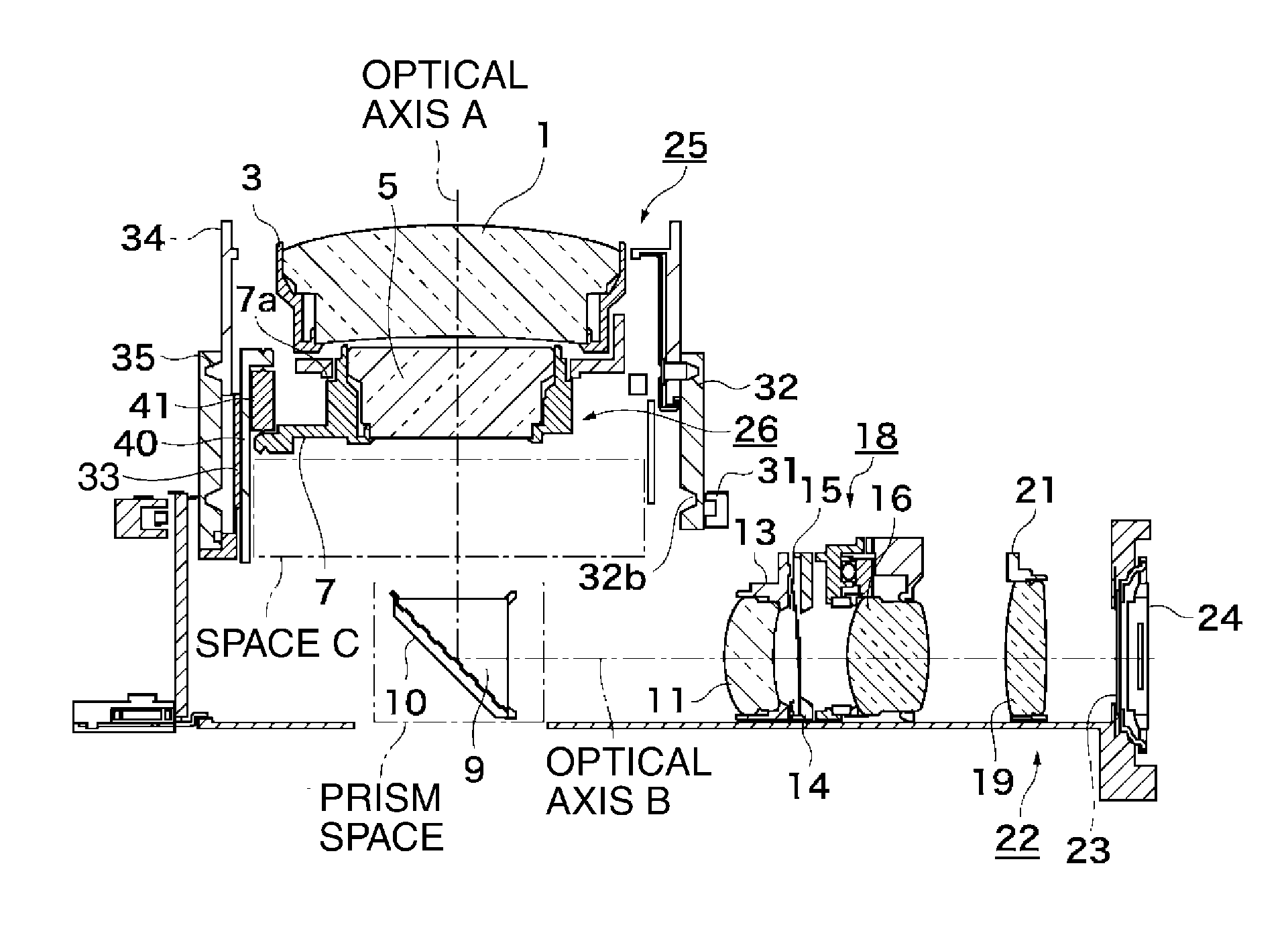
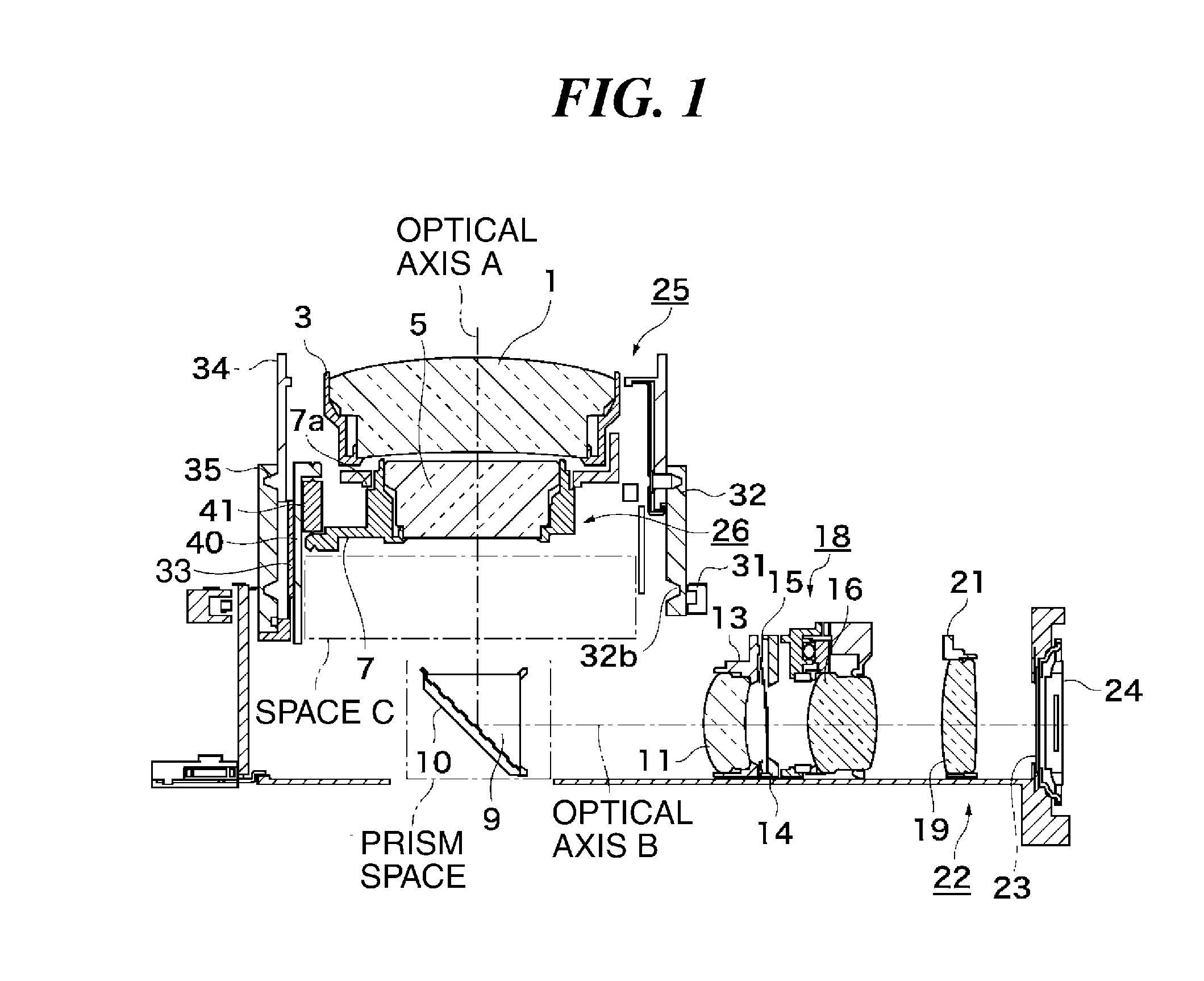
[0036]FIG. 1 is a view of essential parts of an image pickup apparatus according to an embodiment of the present invention, in a wide state in which a photographic optical system (lens barrel) is in a wide angle state.

[0037]A first lens group 25 including a G1 lens 1 is held by a first-group lens holder 3.

[0038]A second lens group 26 including a G4 lens 5 is held by a second-group lens holder 7.

[0039]The first lens group 25 and the second lens group 26 form at least two object-side lens groups disposed toward an object side.

[0040]The second-group lens holder 7 is urged by action (resilient force) of a spring 41 in a direction along the optical axis A to be brought into abutment with a positioning abutment portion 40a (see FIG. 7) of a second-group holding member 40, whereby the second-group lens holder 7 is securely coupled to the second-group holding memb...


PUM


Abstract

An image pickup apparatus enabling construction of a small bending optical system with high magnification. A first lens group is movably disposed toward an object on a first optical axis. A second lens group is movably disposed radially inward of the first lens group. The second lens group comprises a drive frame drivingly controlled along the first optical axis and a lens holding frame for holding the second lens group. A prism is disposed on the first optical axis, for bending light incident on the prism to thereby guide the light along a second optical axis. The prism is retracted along the second optical axis in a non-shooting state. In the non-shooting state, the second lens group is retracted and accommodated in a space defined by the drive frame and the lens holding frame and a space occupied by the prism in a shooting state.

Description

BACKGROUND OF THE INVENTION[0001]1. Field of the Invention[0002]The present invention relates to an image pickup apparatus provided with an optical member drive mechanism for driving an optical member using a bending optical system, and a lens barrel including a bending photographic optical system comprised of a plurality of lens groups.[0003]2. Description of the Related Art[0004]Conventionally, a technique related to the above-mentioned type of image pickup apparatus has been disclosed in Japanese Patent Laid-Open Publication No. H11-271829.[0005]More specifically, a camera (image pickup apparatus) disclosed in Japanese Patent Laid-Open Publication No. H11-271829 is provided with a one-sided cam ring open forward in an optical axis direction, and second and third group lenses are spring-urged toward the cam face of the cam ring, whereby the group lenses are drivingly controlled in the optical axis direction in accordance with a zooming operation.[0006]Further, in the above-mention...

Claims


Application Information

Patent Timeline
21 Jan 2010
Publication
US20100014171A1
IPC
G02B7/02; G02B17/08
CPC
G02B5/04; G02B7/023; G02B15/161; G02B7/102; G02B15/142
Inventors
YAMAMOTO, HARUSHIGE; ICHINO, KAZUSHIGE