Light irradiation apparatus

a technology of light irradiation apparatus and light irradiation area, which is applied in the direction of lighting support devices, lighting applications, instruments, etc., can solve the problem of not being able to adjust the size of the light irradiation area

Inactive Publication Date: 2010-01-21
MITSUBISHI CHEM CORP
View PDF7 Cites 85 Cited by
  • Summary
  • Abstract
  • Description
  • Claims
  • Application Information

AI Technical Summary

Benefits of technology

[0033]Thus, according to the present invention, the light irradiation apparatus can adjust widening/narrowing of the light irradiati

Problems solved by technology

However, each of what were described focused only on efficiency of casting the light from the LED forward, it cannot ma

Method used


Image

  • Light irradiation apparatus
  • Light irradiation apparatus
  • Light irradiation apparatus

Examples


first embodiment

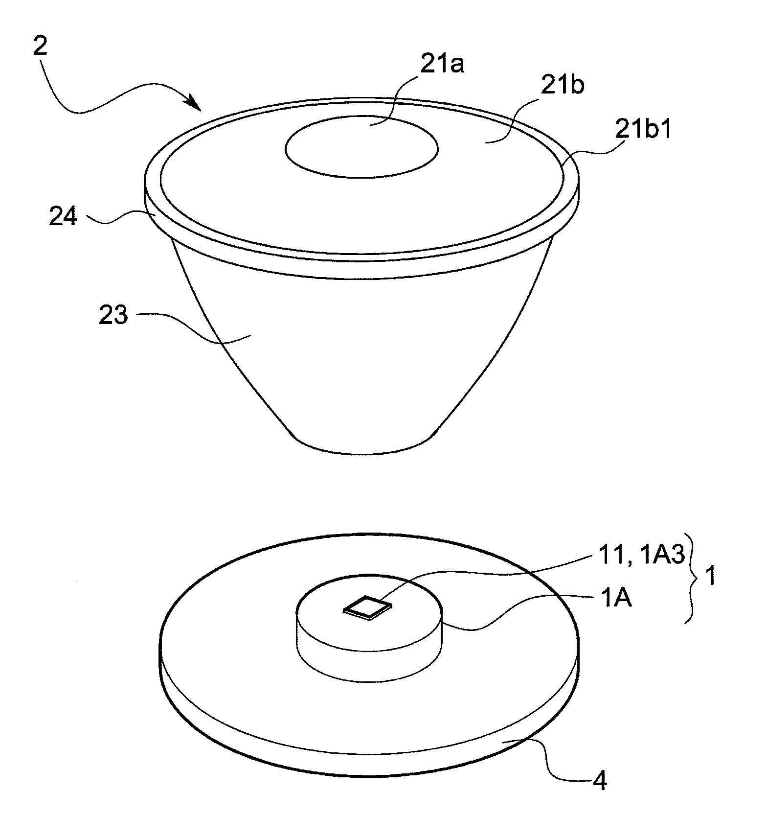
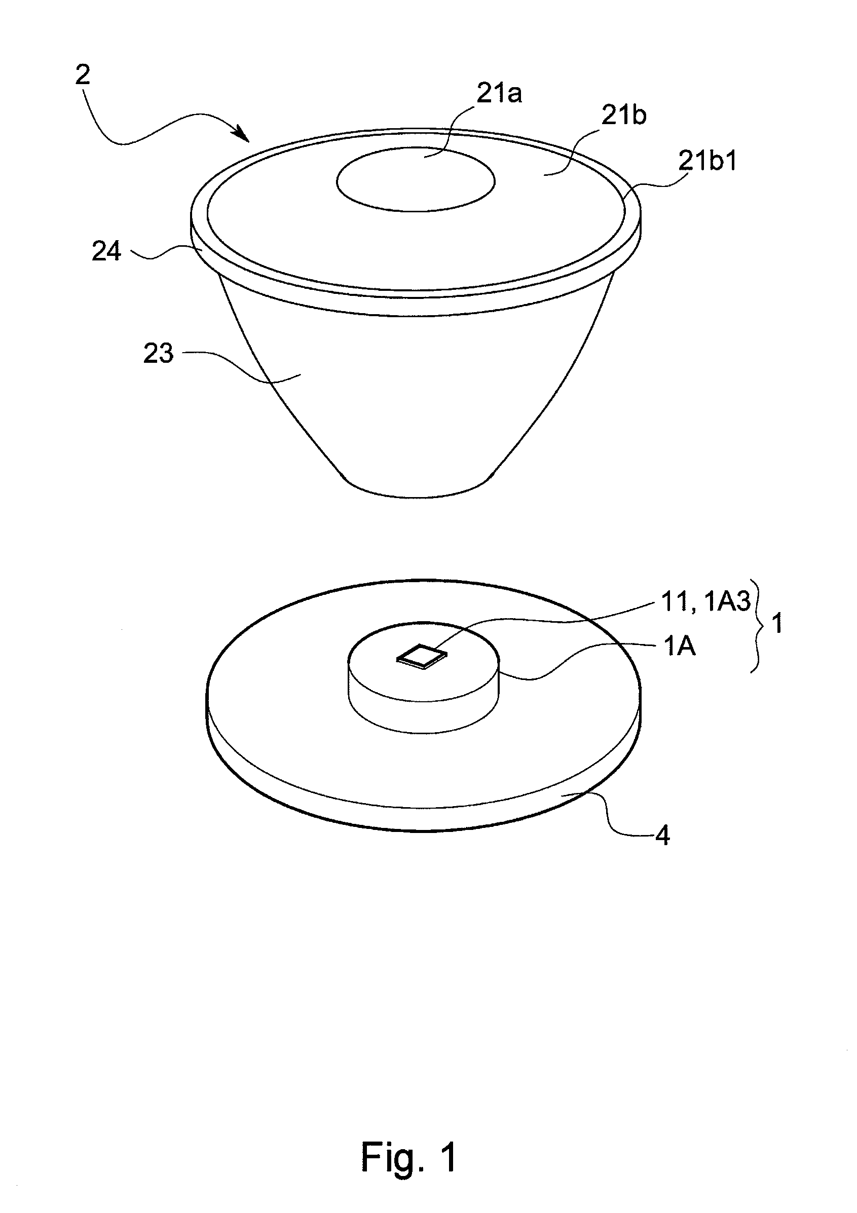
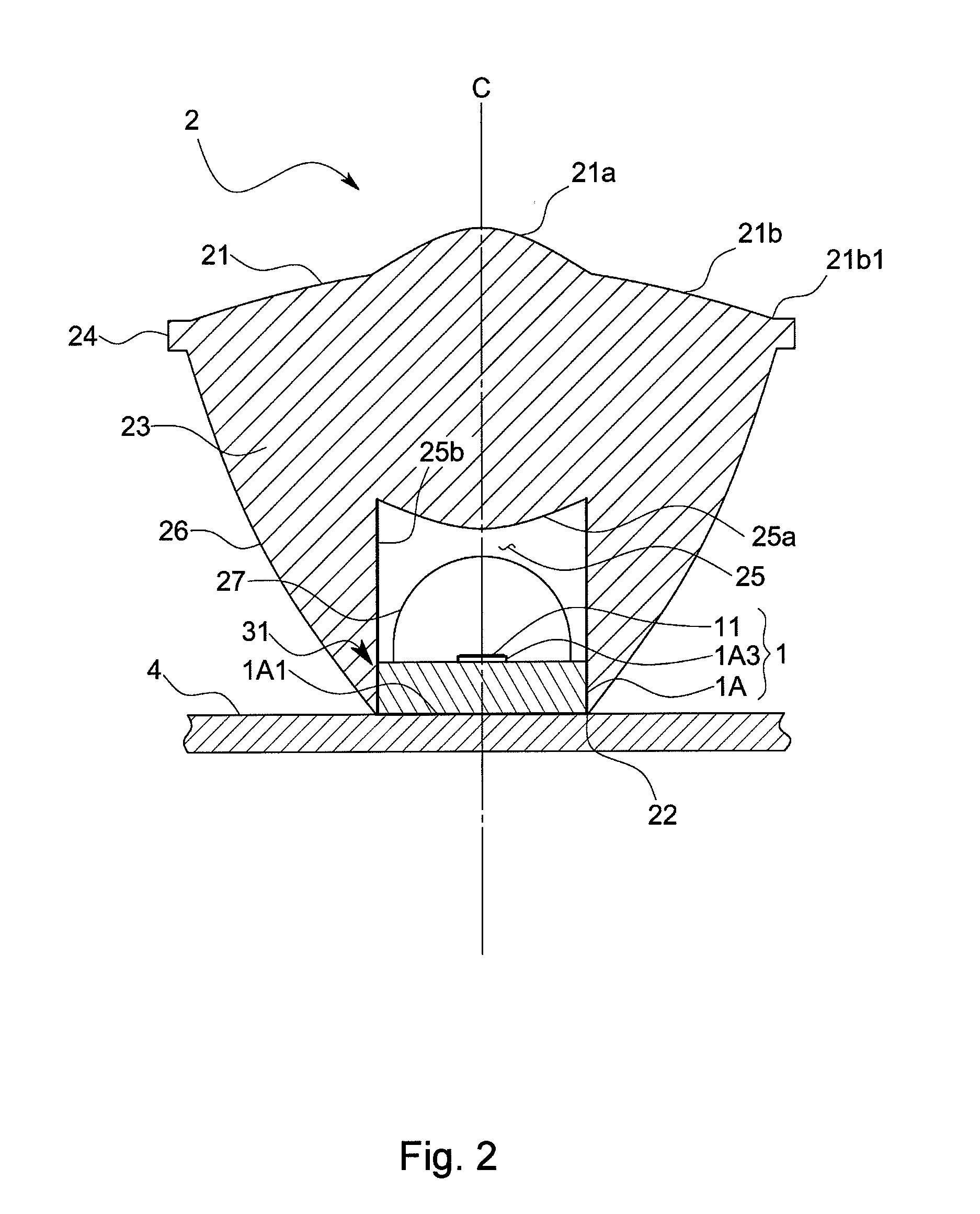
[0057]The light irradiation apparatus according to the present embodiment has an LED package 1 including an LED 11 that is a light source, an optical unit 2 that receives light emitted from the LED 11 and emits it from its apical surface 21, and an unillustrated casing for housing and holding these LED package 1 and optical unit 2.

[0058]The each part will be described in detail. The LED package 1 has a supporting body 1A and the LED 11 supported on an apical surface 1A1 of the supporting body 1A, and the both are fixed to the casing.

[0059]The supporting body 1A is, as shown in FIGS. 3 and 4, is composed of a main body part 1A2 in the shape of a plate of a uniform thickness and a mount member 1A3 that is a bulge part provided on the main body part 1A2, and is mounted on a wiring board 4. The main body part 1A2 is, for example, a member in a substantially circular shape in a plan view having a predetermined thickness and has a lamination structure of a wiring layer S1, an insulating l...

second embodiment

[0072]Hereafter, a second embodiment will be described referring to the drawings. Incidentally, members that correspond to the members in the first embodiment are denoted by the same symbols, respectively.

[0073]As shown in FIGS. 9 and 10, the light irradiation apparatus according to the present embodiment has a substrate 5, a plurality of light irradiation blocks 6 and the same number of concave lenses 71 as the light irradiation blocks 6 that are supported by the substrate 5, and a position adjustment mechanism 9 for setting a distance between the light irradiation block 6 and the concave lens 71.

[0074]The substrate 5 is a metallic member in roughly a cylinder shape one of whose end faces is blocked with a thick bottom plate 51, and radiation-fin F is provided in the bottom plate 51 integrally.

[0075]The light irradiation block 6 has the LED package 1 and the optical unit 2 fixed to the LED package 1, and a plurality of light irradiation blocks 6 are attached to the wiring board 4 o...

third embodiment

[0082]Hereafter, a third embodiment will be described referring to the drawings. Incidentally, members that correspond to the members in the first and second embodiments are denoted by the same symbols.

[0083]A light irradiation apparatus according to the present embodiment has the substrate 5, a plurality of light irradiation blocks 6 and the same number of concave lenses 71 as the light irradiation blocks 6 that are supported by the substrate 5, and the position adjustment mechanism 9 for setting a distance between the light irradiation block 6 and the concave lens 71, as shown in FIGS. 13 and 14.

[0084]The substrate 5 is, for example, a metallic member in the shape of a disc having thermal conductivity and heat dissipation.

[0085]The light irradiation block 6 has the LED package 1 and the optical unit 2 fixed to the LED package 1. The plurality of light irradiation blocks 6 are fixed to the wiring board 4 on a circle thereof at equal intervals. Since these LED package 1 and optical ...


PUM


Abstract

The invention provides a light irradiation apparatus that can adjust widening/narrowing of a light irradiation area and can guide almost whole of light emitted from an LED to the light irradiation area.
The apparatus has an LED 11 and an optical unit 2 for making light for the LED 11 pass through itself and emit from its apical surface 21, and is equipped further with a supporting body 1A for holding the LED on the apical surface and a position adjustment mechanism for adjusting a relative position of the optical unit 2 to the LED 11 along an optical axis C direction. The apparatus is configured so that the potion adjustment mechanism make the optical unit 2 move relative to the LED 11 between a proximity position P1 at which a part or the whole of the supporting body 1A is housed in a base end recess 25 and a clearance position P2 at which substantially whole of the supporting body 1A comes out of the base end recess 25 so that the apical surface of the supporting body 1A and a base end face 22 of the optical unit 2 become substantially the same height.

Description

BACKGROUND OF THE INVENTION[0001]1. Field of the Invention[0002]The present invention relates to a light irradiation apparatus using an LED as a light source that is preferably used for spot illumination for product inspection, plant cultivation, or exhibits (pictures, foods, etc.).[0003]2. Description of the Background Art[0004]Recently, the high-intensity LED called the power LED, the blue LED, etc. have been developed, and along with these developments the LED are having greatly enlarged applications. For example, as a spot light irradiation apparatus for product inspection that is used for detecting flaws of a product and reading a mark thereof, conventional one using a halogen lamp as its light source has been used. However, in recent years, irradiation apparatuses each of which uses the LED that is superior in a life, luminous intensity stability, fast response, efficiency, etc. have been developed. Moreover, since the LED emits a less amount of heat and is also excellent in c...

Claims


Application Information

Patent Timeline
IPC IPC(8): F21V9/00F21V17/02F21V7/00F21V5/00H01L33/58H01L33/60
CPCF21V5/00G02B19/0061F21V5/04F21V7/0091F21V7/04F21V13/04F21V14/00F21V14/02F21V14/06F21V21/30F21V27/02F21W2131/411F21Y2101/02H01L33/58H01L33/60G02B19/0028F21V5/008F21Y2115/10F21V9/40H01L2224/48091H01L2924/00014
Inventor YONEDA, KENJISAITO, MITSURU
Owner MITSUBISHI CHEM CORP
Why Eureka
Try Eureka