Splicing of Encrypted Video/Audio Content

a technology of encrypted video and audio, applied in the field of systems and methods for splicing digitally encoded video and/or audio, can solve the problems of video and audio streams not being available in clear, video and audio streams not meeting the buffer model of the mpeg decoder, and noticeable lip sync problems

Active Publication Date: 2010-01-21
TRITON US VP ACQUISITION CO
View PDF12 Cites 48 Cited by
  • Summary
  • Abstract
  • Description
  • Claims
  • Application Information

AI Technical Summary

Problems solved by technology

When two segments of an MPEG compressed video stream, both of which are compliant with the MPEG decoder buffer model, are “glued” together, then in general the resulting MPEG stream will not comply with the MPEG decoder buffer model.
This shift can lead to noticeable lip sync problems, especially due to accumulation of the shift after a number of splices.
However, there are many instances when splicing is desired, but the PES packets have already been encrypted, and thus the video and audio streams are not available in the clear.

Method used


Image

  • Splicing of Encrypted Video/Audio Content
  • Splicing of Encrypted Video/Audio Content
  • Splicing of Encrypted Video/Audio Content

Examples


example embodiments

Description of Example Embodiments

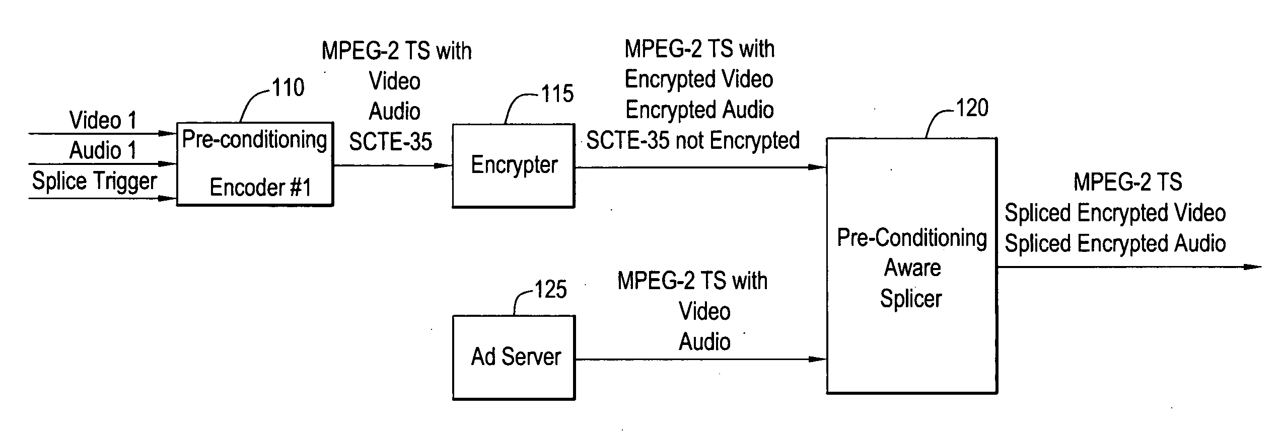
[0037]FIG. 1 shows a block diagram of one possible implementation of the present invention (ad insertion). A pre-conditioning encoder 110 receives video and audio signals, as well as a splice trigger that is indicative of a splice event that is to occur in the near future. The encoder 110 may encode the video and audio in accordance with a video / audio compression standard, such as MPEG-2 and output an MPEG-2 transport stream. The splice trigger is transformed into a well-known SCTE-35 cue message. The encoded elementary streams (ES) are passed to Encrypter 115, which encrypts the payloads of the individual packets that comprise the transport stream. The SCTE-35 cue messages are preferably not encrypted (if they are, sufficient information must be provided to allow the splicer to decrypt them). Note that the splice trigger could also be transported from the encoder to the splicer by a means other than SCTE-35.

[0038]The thus-encrypted transport stream...

example 1

RateAN, (DTS−STC)A=(DTS−STC)N (FIG. 18)

[0223]Since the DTS−STC distance of the ad is already identical to that of the network feed, there is no shift in decoder buffer delay for the ad. At the splice out point, the decoder buffer level drops to that of the original ad. At the network in point, the decoder buffer level rises back to that of the network feed.

example 2

RateA=RateN, (DTS−STC)A=(DTS−STC)N (FIG. 19)

[0224]Since the DTS−STC distance of the ad is already identical to that of the network feed, there is no shift in decoder buffer delay for the ad. Since the bit-rate of the ad is also identical to that of the network feed there is no drop in the decoder buffer level around the network out point and no rise around the network in point.


PUM


Abstract

System and method for performing a splice operation on an encrypted or unencrypted MPEG-2 transport stream. A splice trigger is received at a pre-conditioning encoder. In response, the encoder generates, e.g., an SCTE-35 cue message that is intended to be received by a splicer. Also in response to the splice trigger, the encoder encodes/conditions a network feed such that a decoder buffer delay reaches a predefined value at a video frame of the network feed that corresponds to a splice point indicated by the SCTE-35 cue message. The network feed may then be encrypted in a known fashion. At the splicer, another feed is switched into the stream at the splice point, wherein the another feed is encoded such that a decoder buffer delay at a video frame of the another feed corresponding to the splice point is the same as the predefined value. The predefined value is defined as DTS−STC, where DTS is a Decoding Time Stamp and STC is a System Time Clock. The pre-conditioning encoder generates around the splice point audio PES packets that contain a single aligned audio frame.

Description

FIELD OF THE INVENTION[0001]The present disclosure relates to systems and methods for splicing digitally encoded video and / or audio, such as video and audio encoded in an MPEG-2 transport stream.BACKGROUND OF THE INVENTION[0002]As is well-known in the art, MPEG (i.e., MPEG-1, MPEG-2, MPEG-4, H.264) compressed video and audio streams are mapped into MPEG-2 Transport Streams as Elementary Streams (ES) packed into Packetized Elementary Stream (PES) packets, which, in turn, are packed in MPEG-2 Transport Stream (TS) packets. The PES packets contain a PES header which contains, among other things, a Presentation Time Stamp (PTS) and optionally also a Decoding Time Stamp (DTS) (in case the DTS is not present, it is considered equal to the PTS). The DTS tells the decoder when to decode a video / audio frame, while the PTS tells the decoder when to display (i.e., present) the video / audio frame. Both the DTS and PTS values are actually time events that are relative to a time reference that is ...

Claims


Application Information

Patent Timeline
Patent Type & Authority Applications(United States)
IPC IPC(8): H04N7/24
CPCH04N21/23424H04N21/23608H04N21/8547H04N21/4344H04N21/44016H04N21/23895
Inventor BEHEYDT, SAMIEDE LAMEILLIEURE, JANAU, JAMES KA SIN
Owner TRITON US VP ACQUISITION CO
Why Eureka
Try Eureka