Evaporative cooler assisted automotive air conditioning system

a technology of air conditioning system and evaporative cooler, which is applied in the direction of free-cooling system, machine/engine, combustion-air/fuel-air treatment, etc., can solve the problems of high air conditioning load, direct evaporative cooling is counter-productive in some extent, and the sensible heat portion is reduced, so as to reduce the sensible heat portion and reduce the temperature of the wet channel wall

Inactive Publication Date: 2007-07-19
DELPHI TECH INC
View PDF7 Cites 37 Cited by
  • Summary
  • Abstract
  • Description
  • Claims
  • Application Information

AI Technical Summary

Benefits of technology

[0013] The subject invention relates to an automotive air conditioning system including an evaporative cooler in series with the conventional vapor compression system. The purpose of the evaporative cooler is to reduce the sensible heat portion of the air conditioning load handled by the vapor compression air conditioning system. The primary air stream to be conditioned by the evaporator core of the conventional air conditioning system is preconditioned by the evaporative cooler by lowering its dry bulb temperature. During its passage through the evaporative cooler, a fraction of the primary air stream is diverted to the wet channels lined with a water-soaked wicking material. This secondary air stream flowing through the wet channels causes evaporation of the water in the wet channel thereby lowering the temperature of the wet channel walls and thus cooling the primary air stream flowing through the contiguous dry channels. The liquid water required for evaporation is derived from various sources including water condensed from the primary air by the evaporator core of the vapor compression system. A separate provision may be included for water addition when the air conditioning system operates under extremely dry climatic conditions. Under most climatic conditions, the evaporation-assisted air conditioning system is capable of operating without separate water addition.

Problems solved by technology

However, a decrease in the dry bulb temperature is desired to result in lower sensible air conditioning load, as an increase in the absolute humidity is undesired to result in higher air conditioning load.
Thus, direct evaporative cooling is counterproductive to some extent.

Method used


Image

  • Evaporative cooler assisted automotive air conditioning system
  • Evaporative cooler assisted automotive air conditioning system
  • Evaporative cooler assisted automotive air conditioning system

Examples


Embodiment Construction

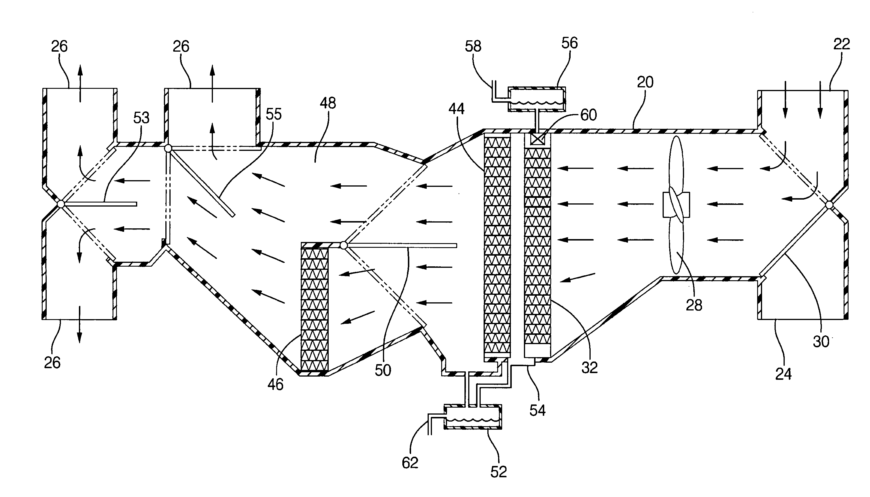
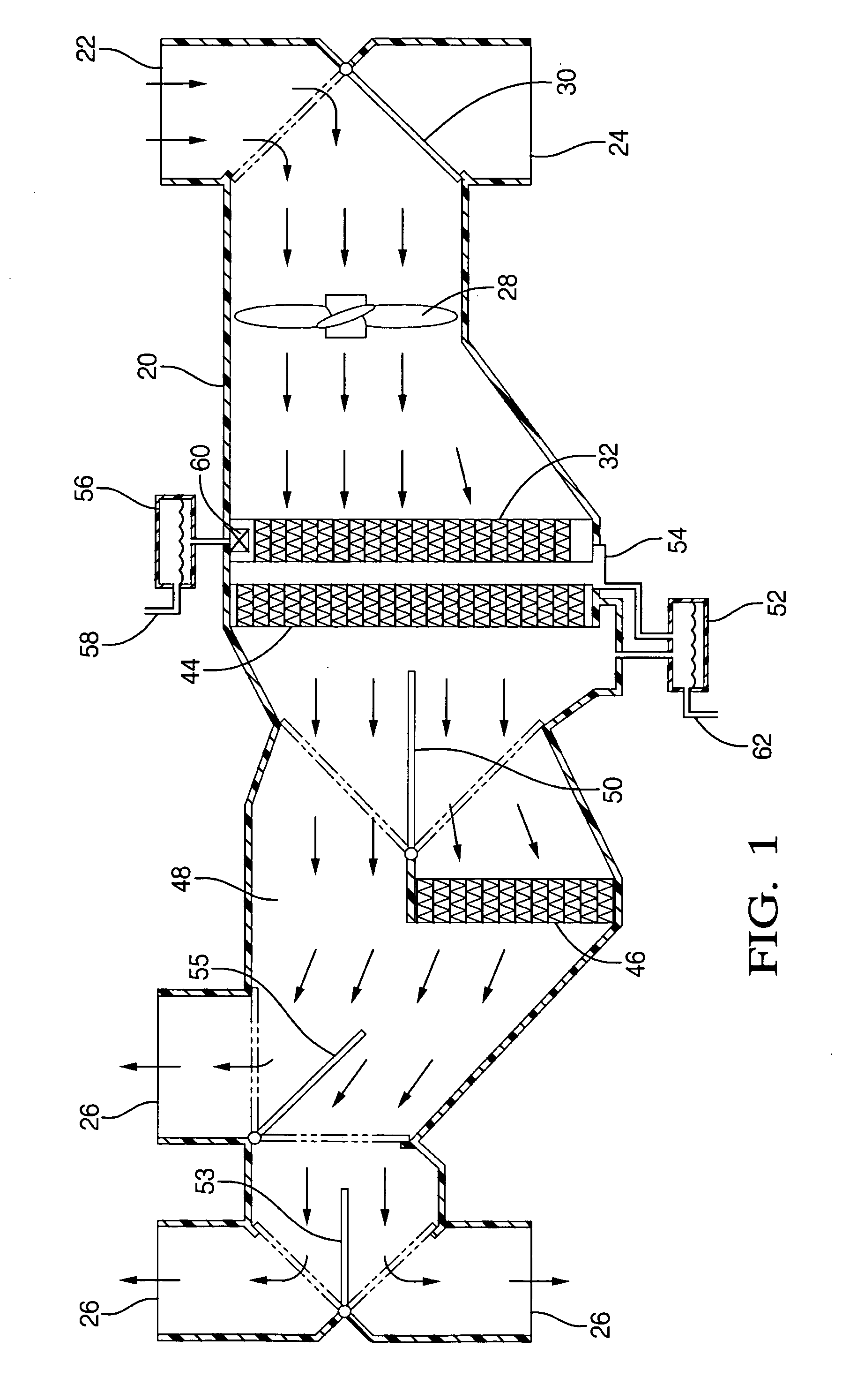
[0021] A heating and ventilating and air conditioning (HVAC) system is illustrated schematically in FIG. 1 and includes a housing 20 presenting an outside air inlet 22 for drawing in outside air and a re-circulated air inlet 24 for drawing in recirculated air from the compartment of an automotive vehicle. The housing 20 also presents conditioned air outlets 26 for proportioning primary air into the compartment of an automotive vehicle, e.g., a vent outlet, a defrost outlet, and / or heater outlet.

[0022] A blower 28 is supported in the housing 20 for moving air through the housing 20. An air inlet valve 30 is supported in the housing 20 downstream of the air inlets 22, 24 for proportioning outside air and recirculated air into a mixture of primary air.

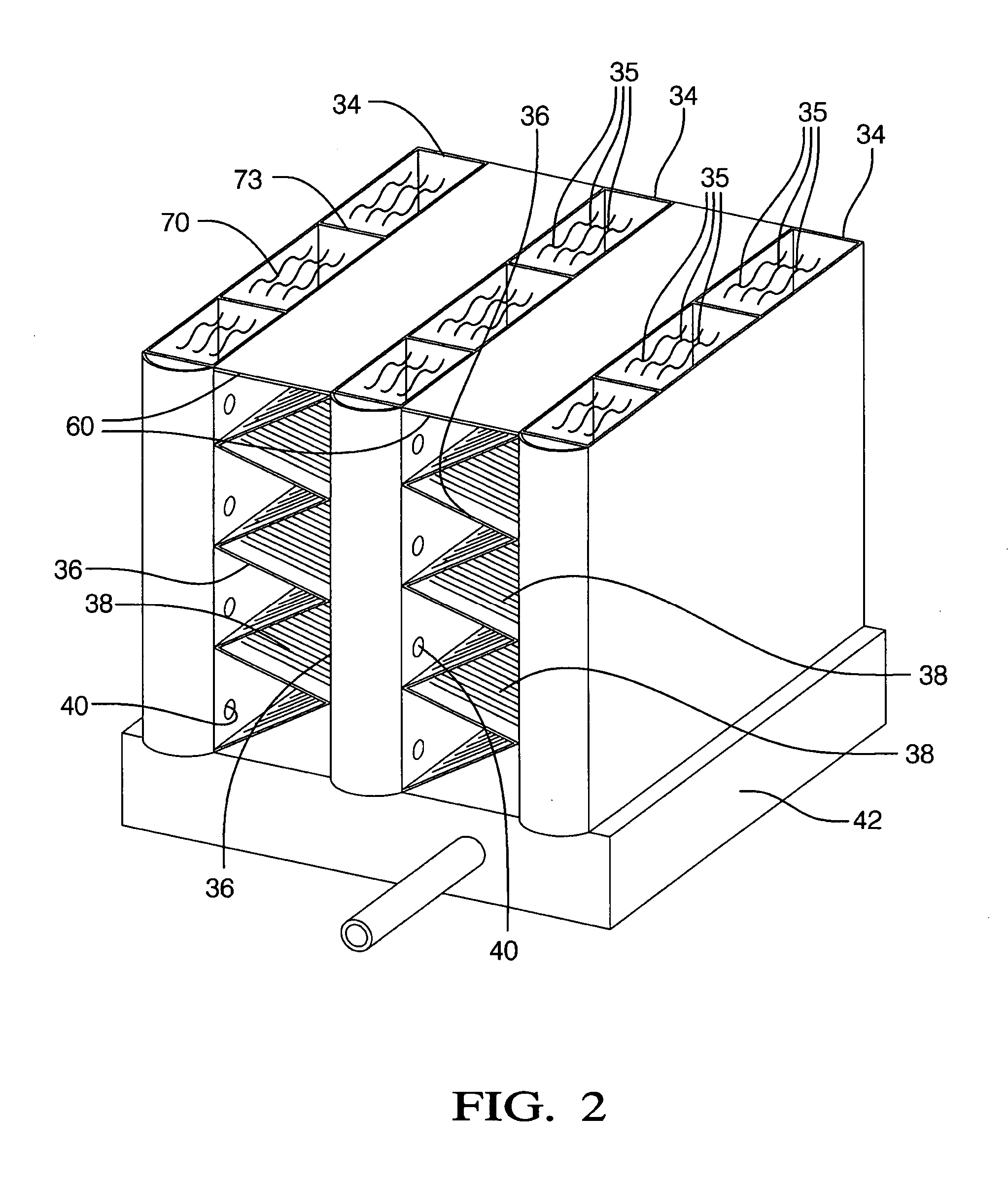
[0023] An evaporative cooler 32 is supported in the housing 20 and defines a plurality of horizontal dry channels for receiving the primary air and a plurality of vertical wet channels extending transversely to the dry channels for rece...


PUM


Abstract

An automotive air conditioning system is disclosed comprising an evaporative cooler in series with the conventional vapor compression system. The evaporative cooler comprises an array of dry channels and a contiguous array of wet channels. The primary air stream to be conditioned by the evaporator of the conventional air conditioning system is preconditioned by the evaporative cooler by lowering its dry bulb temperature without changing its absolute humidity. An evaporator core is supported downstream of the evaporative cooler for receiving the primary air from the dry channels and thereby produces liquid condensate. The system is distinguished by conducting the liquid condensate from the evaporator core to the wicking tank for use in the wet channels of the evaporative cooler.

Description

BACKGROUND OF THE INVENTION [0001] 1. Field of the Invention [0002] The invention relates to an automotive heating, venting and air conditioning (HVAC) system and, more specifically, to a vapor compression air conditioning system augmented by an evaporative cooler operating in series with the air conditioning system. [0003] 2. Description of the Prior Art [0004] The HVAC system to which the subject invention pertains includes a housing with an evaporative cooler supported in the housing upstream of an evaporator core for receiving primary air from dry channels of the evaporative cooler, which also defines a plurality of wet channels extending transversely to the dry channels for receiving secondary air. A wicking tank is disposed under the wet channels for containing liquid and a wicking material is disposed in the wet channels for drawing liquid from the wicking tank into the wet channels. A reservoir is supported by the housing for collecting liquid condensate from the evaporator ...

Claims


Application Information

Patent Timeline
Patent Type & Authority Applications(United States)
IPC IPC(8): B60H1/00B60H1/32F28D5/00F25D17/00
CPCF28F1/126Y02B30/545B60H1/3202F28F1/022F24F1/022F24F5/0035F28D5/02B60H1/3233B60H1/32331Y02B30/54
Inventor BHATTI, MOHINDER SINGHREYZIN, ILYAHOLLASCH, KURT DALE
Owner DELPHI TECH INC
Why Eureka
Try Eureka