

Method of fabricating translucent phosphor ceramics
a technology of translucent phosphor and ceramics, which is applied in the direction of discharge tube luminescnet screens, instruments, other domestic objects, etc., can solve the problems of white light emission of devices and reduce the utility of light-emitting devices
- Summary
- Abstract
- Description
- Claims
- Application Information
AI Technical Summary
Benefits of technology
Problems solved by technology
Method used
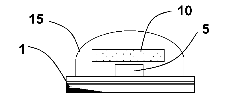
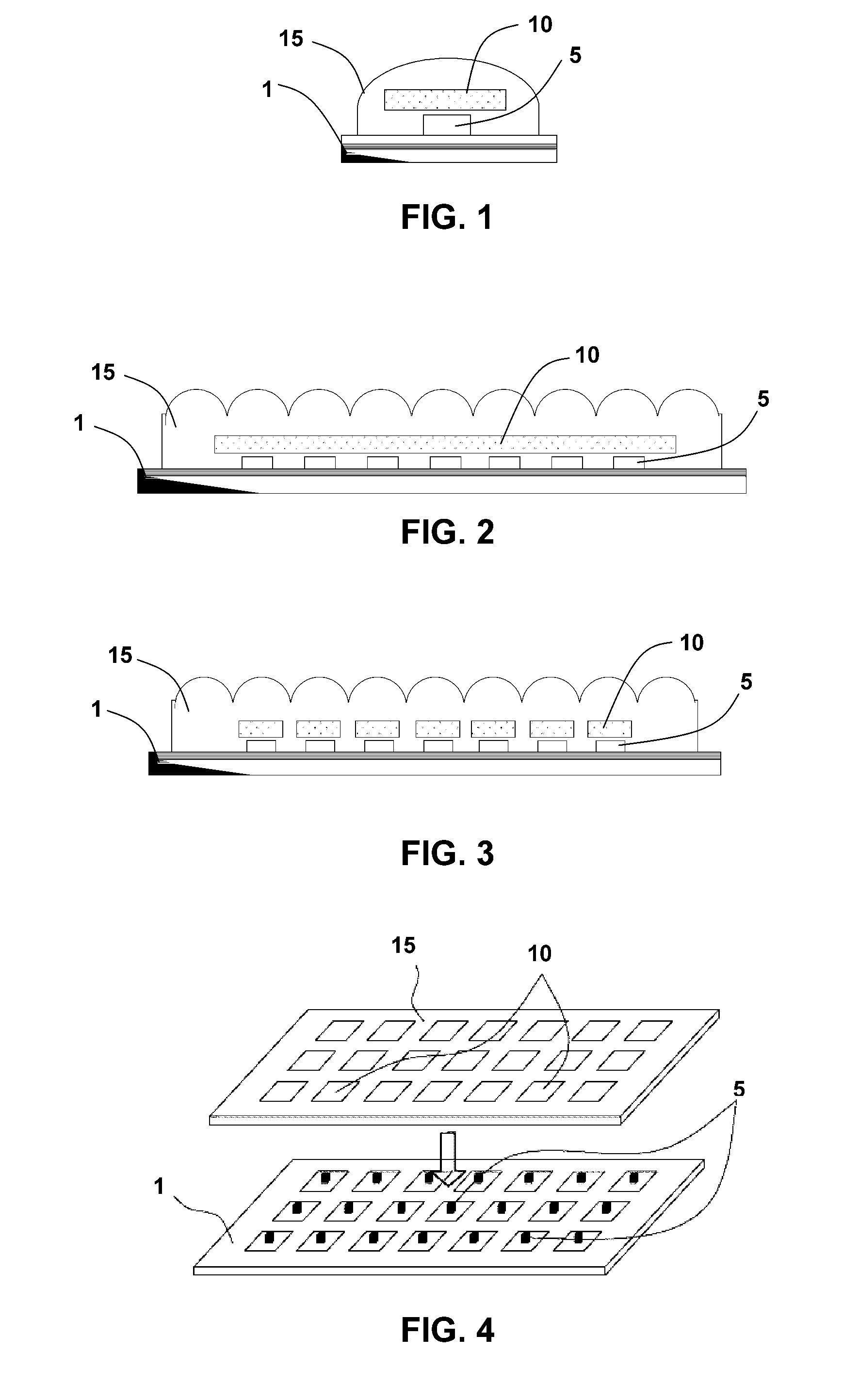
Image

Examples
example 1
[0054]A YAG translucent ceramic compact plate was processed using a pre-conditioned powder prepared as described above with Ce-doping ratio of Ce / Y=0.267 and heated in a N2 / H2 atmosphere at 1200° C. for 2 hrs. The mixture of preconditioned powder, 5 wt. % of poly (vinyl butyral-co vinyl alcohol-co vinyl acetate) (PVB, Sigma-Aldrich, Mw=90000˜120000), and 3000 wt. ppm fumed silica nanoparticles (MH-5, Cabot Corporation) were first sonicated in methanol for 20 min. using a sonicator (XL-2000, Misonix Inc, Farmingdale N.Y.). After completely removing ethanol, the dried powders were gently grinded using mortar and pestle. The disc compacts of 12 mm diameter were molded from either 200 mg or 400 mg mixed powders by applying the compression force of approximately 10 tf at room temperature. The compacts were heated in a high purity alumina tube of 82 mm outer diameter attached to a tube furnace (GSL 1700X, MTI Corporation, Richmond Calif.) heated by a MoSi2 element. Heating intermediate co...
example 2
[0057]The procedure of Example 1 was repeated except that 4.0% TEOS was used as a sintering aid instead of 3000 wtppm SiO2 to make Sample 2. The results are reported in Table 2.
example 3
[0058]The procedure of Example 1 was repeated except that the intermediate compact was heated at 1500° C. for 50 hrs under vacuum. Tt % of the resultant 0.5 mm thick YAG translucent ceramic compact plate (Sample 3) was 61.4%. The density of the plate was 4.45 g / cc. Therefore, a YAG translucent ceramic compact plate with high density was obtained.
PUM
| Property | Measurement | Unit |
|---|---|---|
| temperature | aaaaa | aaaaa |
| temperature | aaaaa | aaaaa |
| temperature | aaaaa | aaaaa |
Abstract
Description
Claims
Application Information