Boring tool with adjustable chamfer cutter

a chamfer cutter and adjustable technology, applied in the field of cutting tools, can solve the problems of inefficiency of operation, increased machining time to finish the workpiece, edge or burr,

Inactive Publication Date: 2010-01-21
STOJANOVSKI DIMITRIJE
View PDF14 Cites 24 Cited by
  • Summary
  • Abstract
  • Description
  • Claims
  • Application Information

AI Technical Summary

Benefits of technology

[0007]It is an advantage of the present invention to provide a boring tool having an elongated cylindrical shank, comprising at least one bore cutting portion mounted proximate to one end of the shank. Each cutting portion including a recessed chip flute formed in the shank and running away from the cutting portion. The tool further comprises a cartridge including a chamfer cutting portion mounted to a body. The body including means for mounting the cartridge to the shank where the cartridge is adjustably coupled to a single chip flute along the chip flute.
[0008]It is another advantage of the present invention to provide a boring tool, comprising an elongated cylindrical shank, an indexable cutting insert having a cutting face and is mounted to the shank proximate to a bottom end of the shank. The shank includes a recessed chip flute adjacent to the cutting insert. The flute runs longitudinally along the shank away from the cutting insert, wherein the flute includes a first wall that is generally collateral with the cutting face. The shank also includes an elongated mounting recess that runs longitudinally along the shank. The mounting recess including a second wall that is parallel, adjacent, and coextensive to the first wall, wherein the first and second walls cooperate to define an elongated rib. The tool further comprises a chamfer cutting cartridge having a body. The cartridge including an indexable chamfering insert and means for retaining the chamfering insert to the body. The body including a pair of spaced mounting lugs extending from the body. The lugs having opposed walls which define a channel, wherein this channel receives the rib such that the first wall and second wall each abut one of the opposed walls and the chamfering insert extends beyond the cutting insert radially.
[0009]It is still another advantage of the present invention to provide a method of adapting an indexable insert boring tool to also perform a chamfering operation, the boring tool having at least one cutting insert and a chip clearance flute running away from the cutting insert along a cylindrical shank. The method comprising the steps of: forming a mounting recess in and along the shank parallel and adjacent to the flute, wherein a portion of the shank remains between the flute and mounting recess to form an elongated rib; providing a cartridge having a chamfer cutter and a pair of spaced mounting lugs defining a channel; mating the cartridge to the shank by straddling the lugs over the rib; and adjusting the chamfering cartridge along the rib such that the chamfer cutter is a desired distance from the cutting insert.
[0010]It is yet another advantage of the present invention that the chamfering cartridge abuts the shank along substantially all of the shank facing surfaces, this abutting engagement prevents cutting debris, such as chips, from jamming in the boring tool.

Problems solved by technology

Currently, cutting tools used to make a hole in a workpiece typically leave a sharp edge or burr at the entry-point of the cutting tool.
This later cutting operation is inefficient and increases machining time to finish the workpiece.

Method used


Image

  • Boring tool with adjustable chamfer cutter
  • Boring tool with adjustable chamfer cutter
  • Boring tool with adjustable chamfer cutter

Examples


Embodiment Construction

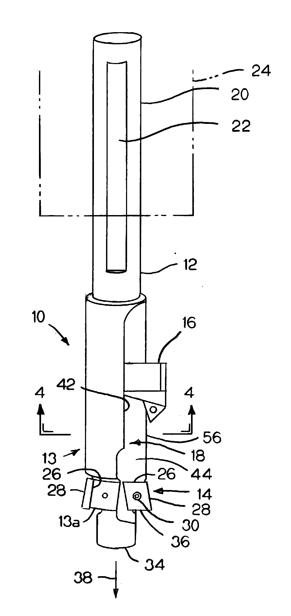
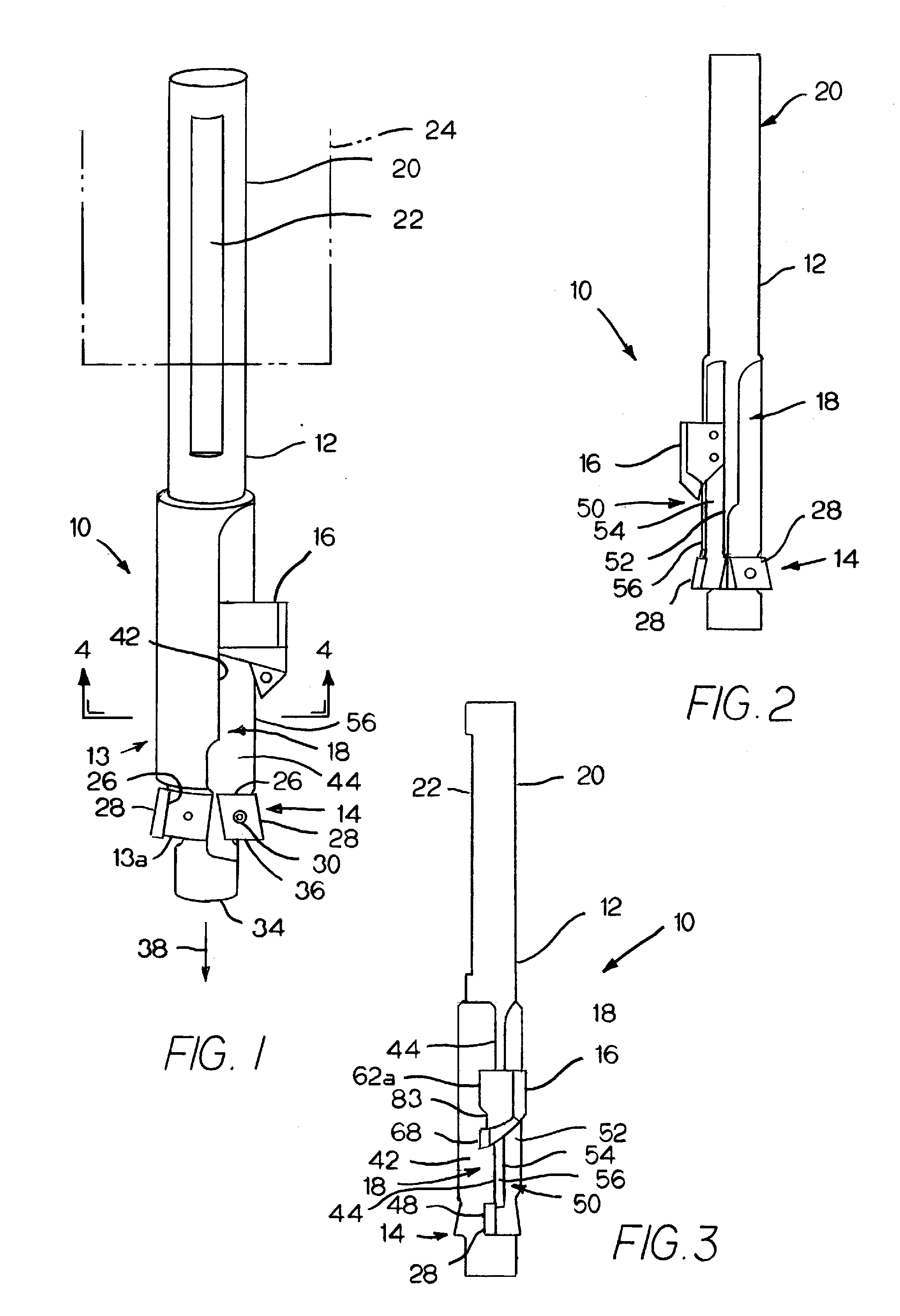
[0019]FIG. 1 illustrates a preferred cutting tool 10 used for cutting or boring a rotating workpiece 5. Tool 10 is illustrated as an exemplary cap screw counterbore used to enlarge a pre-existing hole to accommodate a screw head, however, an individual skilled in the relevant art can readily appreciate that the cutting tool 10 can take the form of substantially any other boring-type cutter, such as a boring bar.

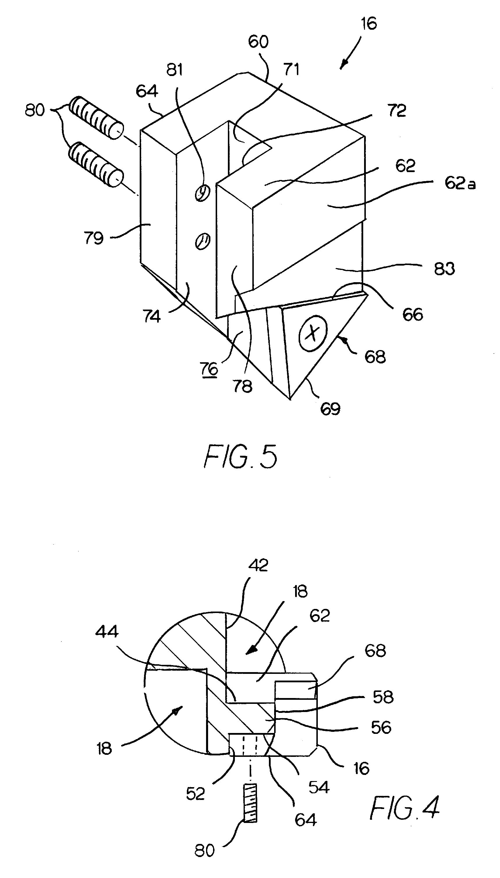
[0020]Tool holder 10 comprises a shank 12, at least one cutting or boring portion 14 fixed proximate to the lower end 13 of the shank 12, and a chamfering cartridge 16. The shank 12 includes a recessed or cut-out chip flute 18 that both provides a relief to allow the cutting portion 14 to engage a workpiece 5 and to provide a channel to direct the cutting debris or chips resulting from a cutting operation out and away from the cutting portion 14 and tool 10. In the preferred embodiment, each cutting portion 14 has a corresponding flute 18.

[0021]The upper end 20 of tool shank ...


PUM

PropertyMeasurementUnit
shapeaaaaaaaaaa
distanceaaaaaaaaaa
timeaaaaaaaaaa

Abstract

A cutting tool having a cutting portion located proximate to one end. The cutting tool including a recessed chip flute formed along the shank of the tool away from the cutting edge. The tool includes a chamfering cartridge which is clamped to the tool shank along the chip flute. The chamfering cartridge performs a chamfering or deburring operation while allowing chips from the cutting portion to pass through the flute and away from the tool and workpiece.

Description

FIELD OF THE INVENTION[0001]The present invention relates to cutting tools and, more particularly, to a boring tool having a removable chamfer cutter mounted thereon.BACKGROUND AND SUMMARY OF THE INVENTION[0002]Currently, cutting tools used to make a hole in a workpiece typically leave a sharp edge or burr at the entry-point of the cutting tool. This edge or burr is dulled or chamfered in a later cutting operation by another tool. This later cutting operation is inefficient and increases machining time to finish the workpiece.[0003]Several forms of chamfering structures are known for mounting a chamfer cutter to a boring tool to reduce the number of cutting operations required to finish a workpiece. Art that has addressed this problem include U.S. Pat. No. 4,533,285 issued Aug. 6, 1985 to Charles A. Jorgensen for a Cutting Attachment For Boring Tool.[0004]The broad purpose of the present invention is to provide a boring tool having an adjustable chamfering cartridge that is mounted ...

Claims


Application Information

Patent Timeline
Patent Type & Authority Applications(United States)
IPC IPC(8): B26D1/12B26D7/18B26D1/00
CPCB23B27/007B23B29/02B23B51/107B23B2210/02B23B2220/04Y10T82/12Y10T407/193Y10T407/24Y10T407/1948Y10T408/62B23B2260/004Y10T83/04
Inventor STOJANOVSKI, DIMITRIJE
Owner STOJANOVSKI DIMITRIJE
Why Eureka
Try Eureka