
Medical implant having at least two data communication channels

a technology of data communication and medical implants, applied in the field of medical implants, can solve problems such as the confrontation of patients and physicians, and achieve the effect of solving the conflict between patients and physicians

Inactive Publication Date: 2010-01-21
BIOTRONIK SE & CO KG
View PDF4 Cites 5 Cited by
  • Summary
  • Abstract
  • Description
  • Claims
  • Application Information

AI Technical Summary

Benefits of technology

[0008]The controller of the medical implant is designed so that it automatically recognizes control commands and / or messages that are received via the second data communication channel and are directed to the programming device. Accordingly, it ensures temporary storage, if necessary, as well as automatic transmission from the medical implant to the programming device as soon as the first data communication channel is active.
[0010]In this way, messages can be transmitted to the attending physician of the respective patient without the physician having to make contact actively with a central service center.
[0011]It is also possible to reliably forward all important information available in a central service center via a patient with an electronic implant to the follow-up care physician without the latter having to have access to the central service center. Furthermore, it is possible to control automatic functions of the programming device based on information set in the central service center, e.g., to prompt a firmware update in a defined serial number group within the context of the next follow-up.
[0012]Likewise, important messages from the manufacturer of electronic implants (e.g., safety advisories) can be transmitted to the follow-up care physician without having to identify the follow-up care physician.
[0018]The invention also includes a medical therapy system having an implant of the type described previously as well as a central service center, which is temporarily connected to the medical implant for data exchange via a data communication channel (the second data communication channel), where the central service center is designed to generate data packets with text messages and / or control commands and programming commands directed to a programming device to be connected to the medical implant, and to transmit them to the medical device when the (second) data communication channel is active. In this sense, a central service center, which is designed to generate data packets containing text messages and / or control commands and programming commands directed to a programming device to be connected to the medical implant, is an independent aspect of the invention. The central service center preferably has an interface for input of text messages intended for a programming device. In this way, a home monitoring physician connected to the central service center can generate messages to a follow-up care physician responsible for the follow-up care of an implant patient and can be certain that this follow-up care physician will receive the message at the proper point in time, namely when he establishes contact with a respective implant by means of a programming device.
[0020]This yields the following advantageous variants of such a system and / or its system components (medical implant, programming device or central service center):

Problems solved by technology

The short range of the wireless data transfer between the medical implant and the external programming device presupposes a close proximity between the implant and the programming device, which results in the patient and physician also confronting one another in such a follow-up examination by a physician.

Method used


Image

  • Medical implant having at least two data communication channels
  • Medical implant having at least two data communication channels
  • Medical implant having at least two data communication channels

Examples


Embodiment Construction

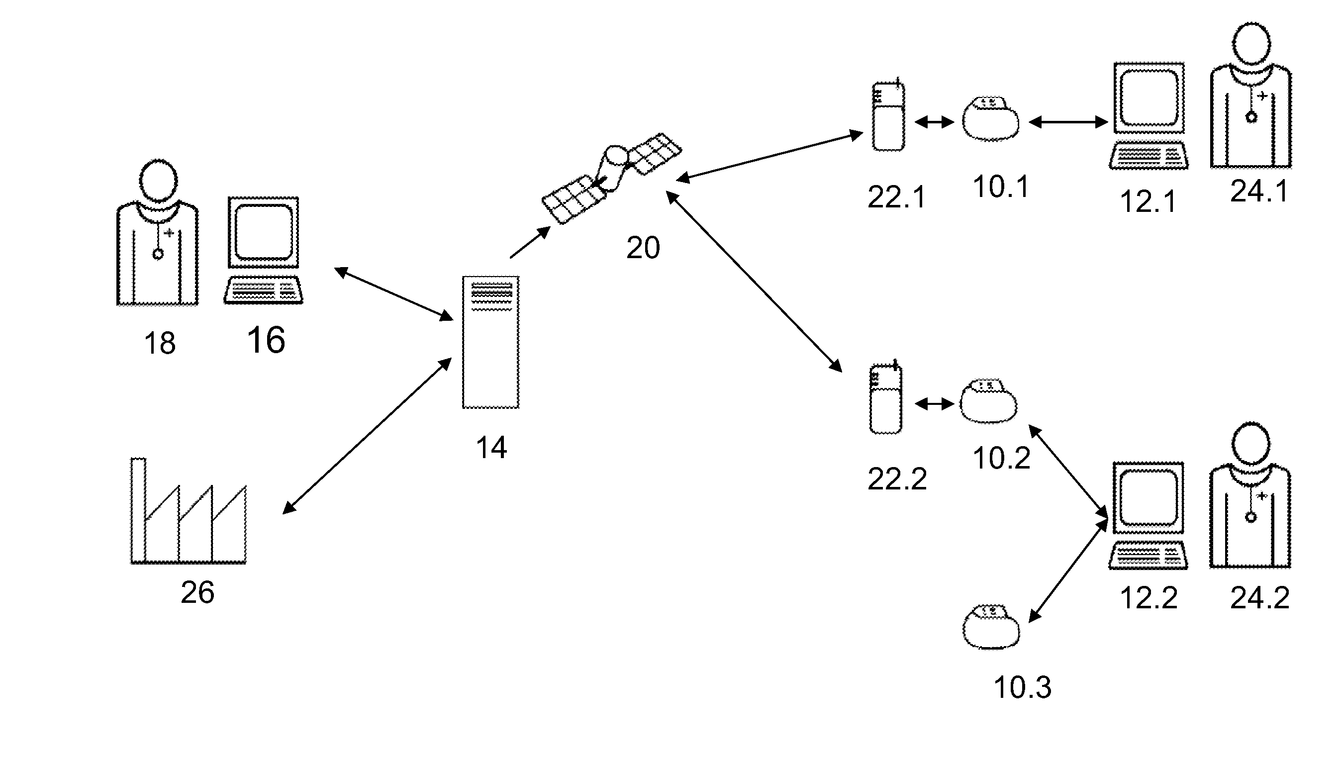
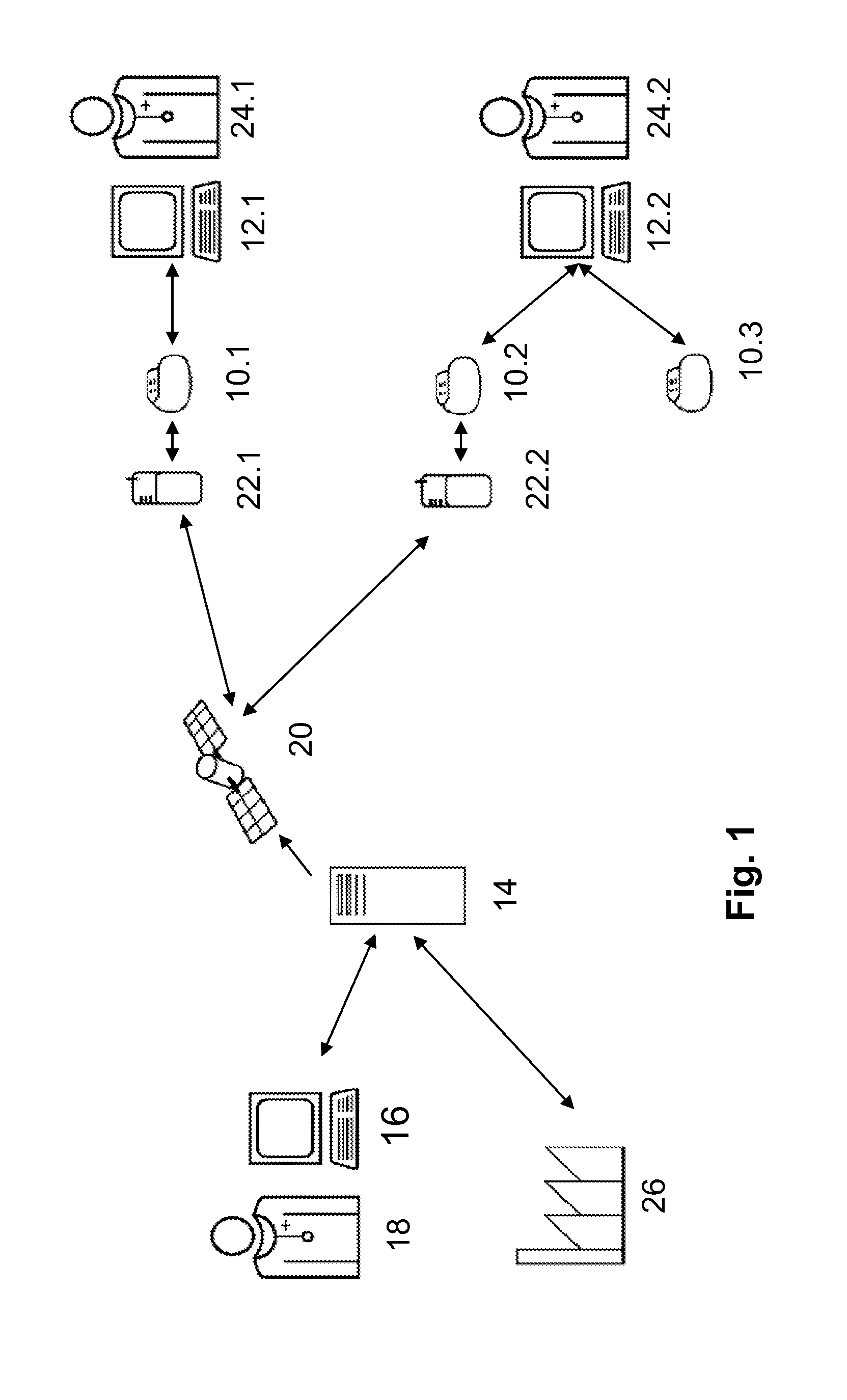
[0038]FIG. 1 shows an overview of an inventive therapy system including an inventive medical implant 10, a programming device 12 assigned to the implant 10 and a central service center having a server 14. For a better understanding, the diagram includes several medical implants 10, shown as 10.1, 10.2, 10.3, plus several programming devices 12, shown as 12.1 and 12.2, plus several patient-individual relay stations 22, shown as 22.1 and 22.2, as well as several follow-up care physicians 24, shown as 24.1 and 24.2. For the functioning of the inventive therapy system, the use of only one of this components shown in multiple forms is sufficient

[0039]The server 14 is connected to a terminal 16 by which a physician 18 has access to the server 14 for remote monitoring of implants 10. The server 14 communicates via a communication link 20 with multiple patient-individual relay stations 22 which are the aforementioned patient devices, for example. These in turn communicate with a respective ...


PUM


Abstract

A medical implant has at least one interface for bidirectional wireless data exchange, a data memory, and a controller. The controller and interface perform a wireless data exchange with at least two different external devices, resulting in at least two different data communication channels, one channel being assigned to data communication with the programming device and a second channel being assigned to data communication with a central service center. The medical implant is also designed to receive control commands and / or messages over the second channel while the second channel is active, and to recognize received control commands and / or messages intended for a programming device, store them temporarily in a memory (if necessary), and forward them to a programming device via the first channel when the first channel is active.

Description

FIELD OF THE INVENTION[0001]The invention relates to a medical implant, i.e., an implantable medical device, such as a heart pacemaker, a cardioverter / defibrillator, or the like.BACKGROUND OF THE INVENTION[0002]Medical implants today often have at least one data communication interface for wireless data exchange with at least one external device, e.g., a programming device, or a so-called patient device which serves as a relay station for data exchange with a central service center.[0003]Programming and scanning of such an implant with the help of a programming device are well known. For example, medical implants such as heart pacemakers and / or cardioverters / defibrillators are often capable of recording physiological data, e.g., intracardiac electrocardiograms or the like, during operation and transferring these data to the programming device in the event of a scan by the programming device. Conversely, it may be possible to reprogram the control of the medical implant with the help...

Claims


Application Information

Patent Timeline
Patent Type & Authority Applications(United States)
IPC IPC(8): A61N1/08G16H40/40G16H40/67
CPCG06F19/3418G06F19/327G16H40/20G16H40/67G16H40/40
Inventor DOERR, THOMAS
Owner BIOTRONIK SE & CO KG
Learn More