
In situ measurements in formation testing to determine true formation resistivity

a technology of resistivity and in situ measurement, which is applied in the field of borehole formation testing and the measurement of formation resistivity, can solve problems such as contamination of fluids

Inactive Publication Date: 2010-01-28
WEATHERFORD TECH HLDG LLC
View PDF26 Cites 15 Cited by
  • Summary
  • Abstract
  • Description
  • Claims
  • Application Information

AI Technical Summary

Benefits of technology

[0011]Comparison of resistivity measurements between the pad and other resistivity devices is not limited to the other resistivity devices being on the same tool. The comparison resistivity measurement that the pad is trying to match could be provided from other sources then just another resistivity measurement made at the same time. The desired formation resistivity value can obtained from measurement made earlier in the drilling of the well, or could obtained from a nearby well and sent from the surface to the tool, or could be pre-stored in the tool prior to entering the wellbore, if this information is already known and once the desired pad resistivity is met, the fluid can be diverted to a sample chamber, or to other fluid property measuring devices in the tool. A key feature of this pad resistivity measurement is the time savings that would be realized from not having to transmit the information to the surface, do the comparison and then transmit new commands to the tool to divert the fluid flow coming from the formation. By enabling the tool to make the decision on its own, significant rig time can be saved.

Problems solved by technology

If resistivity varies as a function of time, this typically indicates that the fluid is contaminated.

Method used


Image

  • In situ measurements in formation testing to determine true formation resistivity
  • In situ measurements in formation testing to determine true formation resistivity
  • In situ measurements in formation testing to determine true formation resistivity

Examples


Embodiment Construction

[0019]Basic principles of the of the borehole formation testing apparatus and methods for making formation in-situ measurements are disclosed in detail using an exemplary system embodied to measure resistivity.

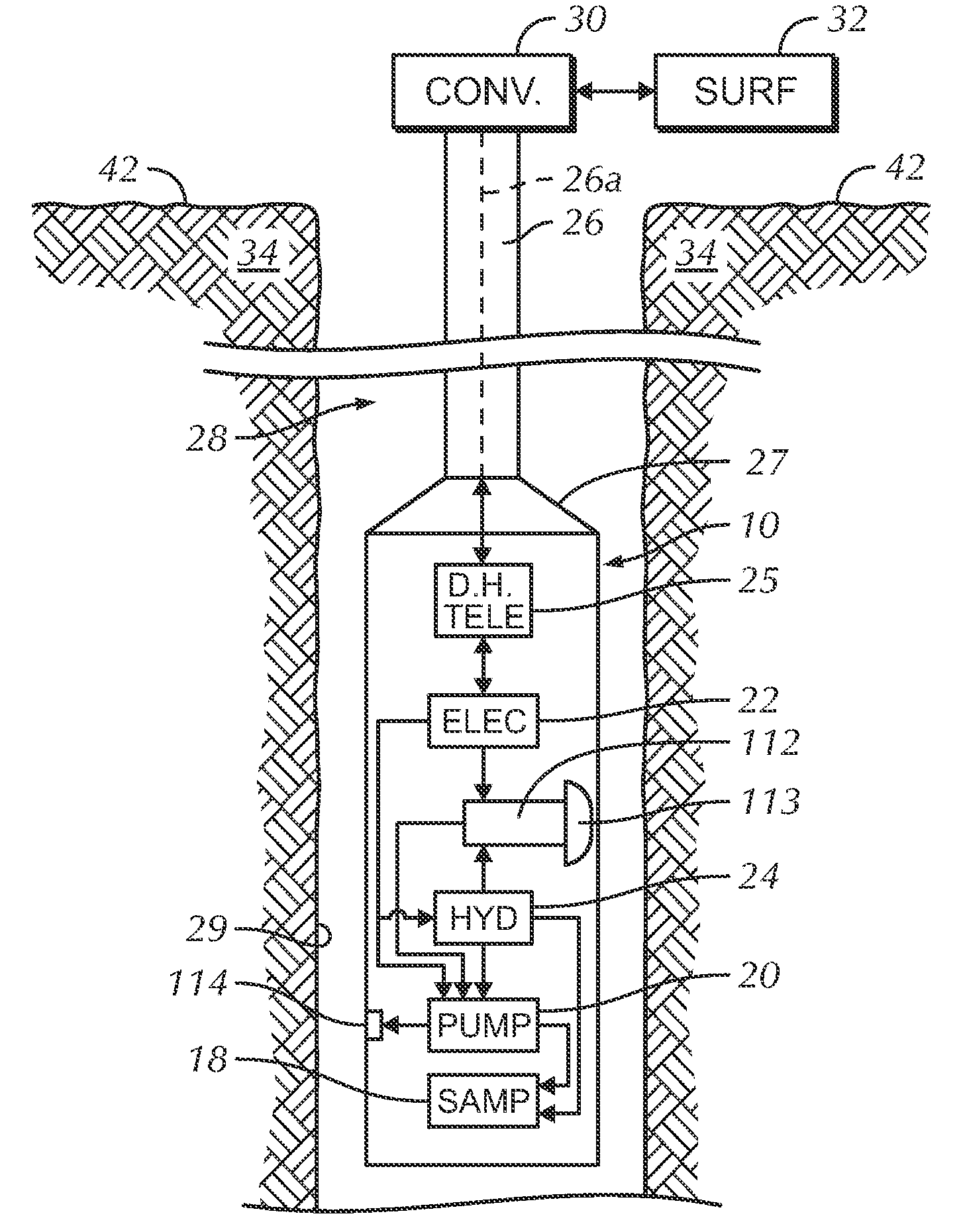
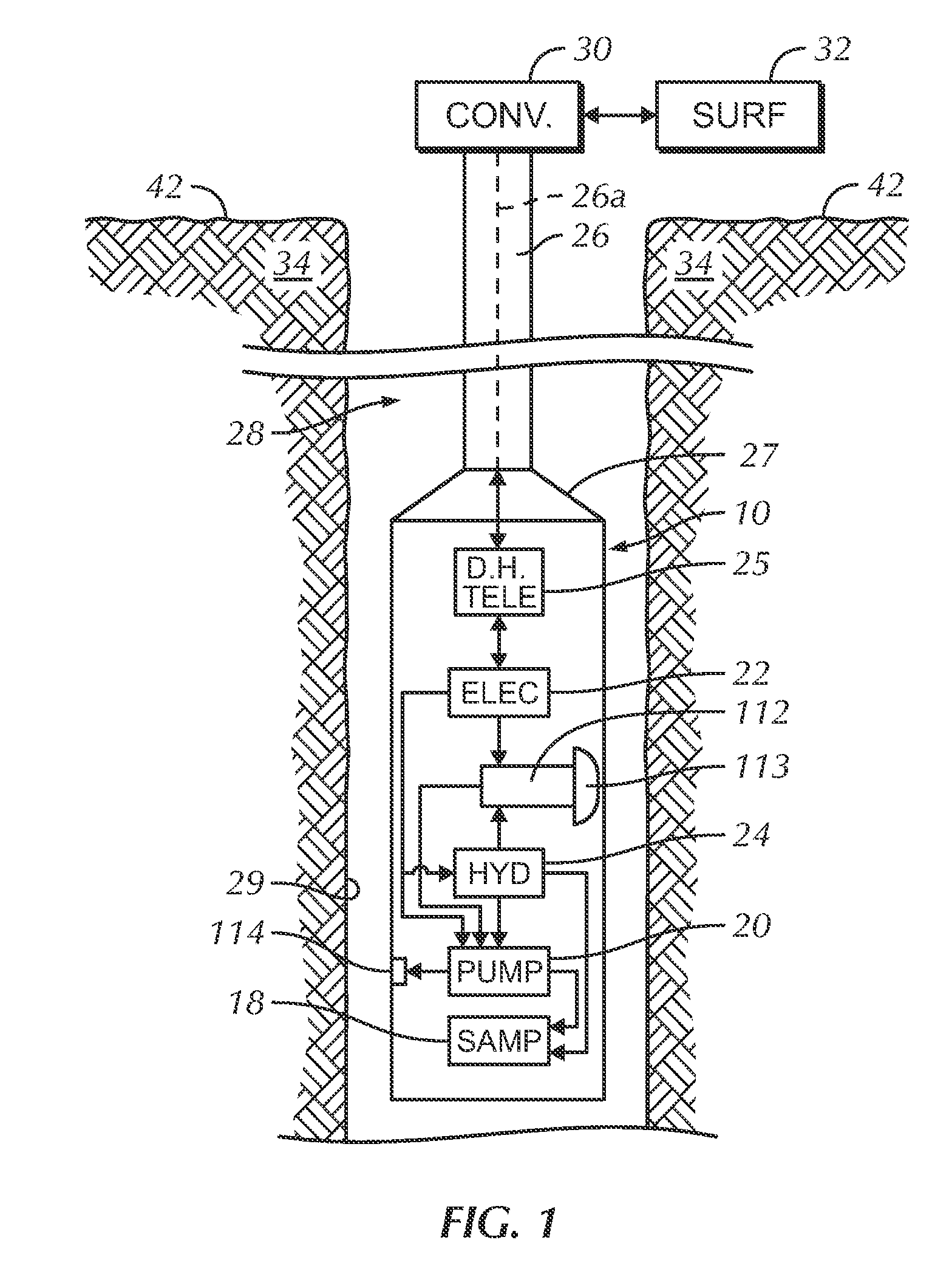
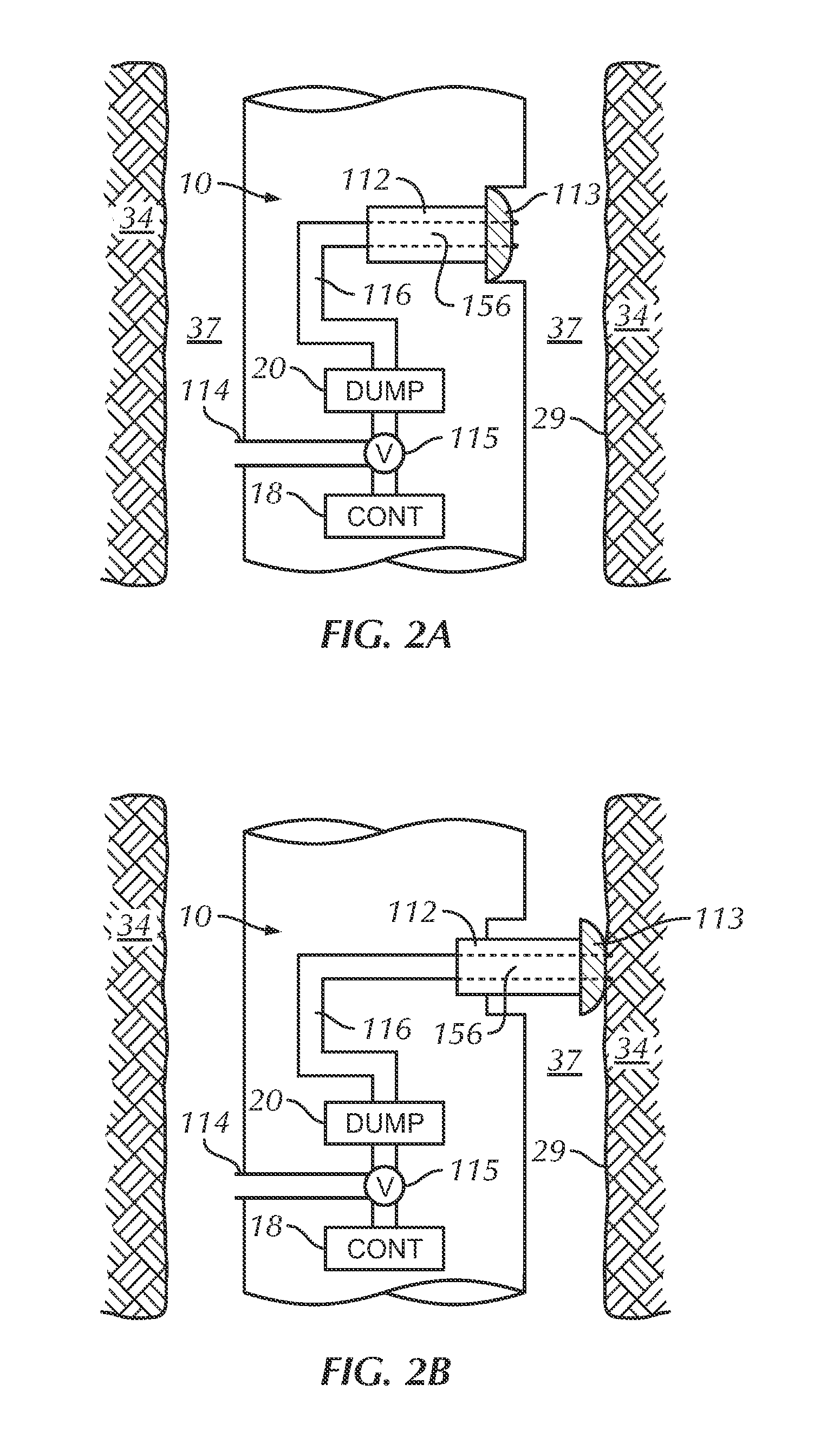
[0020]FIG. 1 illustrates conceptually the major elements of a formation tester system operating in a well borehole 28 that penetrates earth formation 34. The formation tester tool is denoted as a whole by the numeral 10. The tool 10 comprises probe assembly radially extendable from the tool 10 and a probe assembly comprising a probe structure 112 terminated by a pad 113, at least one sample carrier 18, a pump 20, hydraulics 24 to extend and retract the pad assembly and to operate valves within the formation tester, an electronics section 22, and a downhole telemetry element 25. Details of the radially extendable probe assembly comprising a probe structure 112 terminated by a pad 113 are disclosed in previously referenced U.S. Pat. No. 6,301,959 B1 and U.S. patent application S...


PUM


Abstract

A borehole formation testing system that measures resistivity of near borehole formation in situ rather than the measuring resistivity of fluid drawn into a formation tester tool. A radially extendable probe assembly contacts and forms a hydraulic seal with the wall of a borehole using a pad. Electrode contacts are disposed on the contact surface of the pad and electrically contact the near borehole formation. Response of the electrode contacts are used to determine resistivity of the near borehole formation. This resistivity is with a deeper formation resistivity measurement to determine if virgin formation fluid is at or in the vicinity of the pad. Alternately, a plurality of resistivity measurements is made at the formation tester pad and virgin formation fluid at or near the pad is determined from the rate of change of the plurality of resistivity measurements.

Description

FIELD OF THE INVENTION[0001]This invention is related to borehole formation testing and the measure of resistivity of formation. More particularly, the invention is related to the measure of resistivity of formation contacted by a formation tester pad and comparison of this measure with a deeper formation resistivity measurement to determine if virgin formation fluid is at or in the vicinity of the formation tester tool pad fluid port. Alternately, a plurality of resistivity measurements is made at the formation tester pad and virgin formation fluid at or in the vicinity of the formation tester tool pad is determined from the rate of change of the plurality of measurements.BACKGROUND[0002]A variety of systems are used in borehole geophysical exploration and production operations to determine chemical and physical parameters of materials in the borehole environs. The borehole environs include materials, such as fluids or formation matrix, in the vicinity of a borehole as well as mate...

Claims


Application Information

Patent Timeline
Patent Type & Authority Applications(United States)
IPC IPC(8): E21B47/00
CPCE21B47/102G01V3/20E21B49/10E21B47/113E21B49/06G01V3/18E21B49/00
Inventor MCGREGOR, M. DOUGLAS
Owner WEATHERFORD TECH HLDG LLC
Learn More